Laminated wrench construction system

Inactive Publication Date: 2005-12-15
MARKS JOEL +1
View PDF10 Cites 6 Cited by
  • Summary
  • Abstract
  • Description
  • Claims
  • Application Information

AI Technical Summary

Benefits of technology

[0010] In the present invention an improved all-gear drive system for a slide adjustable wrench is disclosed. A rack and pinion gear set converts linear motion of a slide switch to rotational motion of a gear shaft. A further drive shaft translates the rotational motion to a worm gear shaft. A laminated steel housing contains a molded or cast body which in turn contains the gears and other components. The gears are discrete rigid elements that are easily handled during assembly and readily held in repeatable positions in use. The gears may be produced by low cost molding, powder metal, or die casting methods. A gear rack is slidably fitted in a channel of the body and linked to the slide switch. A pinion rotates about a fixed axis within the housing and mates to the gear rack

Problems solved by technology

A problem in designing a slide adjustable wrench is to provide an adequate amount of jaw travel within a reasonable range of motion of sliding.
However if this angle exceeds by much that used in conventional adjustable wrenches, the jaw will not reliably hold a position under force.
At increasing reductions however gear 42 will become impractically small or gear 56 very large.
However the practical steepness is limited by friction to about 30° off-axis.
A further problem with a helical shaft design is that such a shaft is not easily produced by simple moldi

Method used


Image

  • Laminated wrench construction system
  • Laminated wrench construction system
  • Laminated wrench construction system

Examples


Embodiment Construction

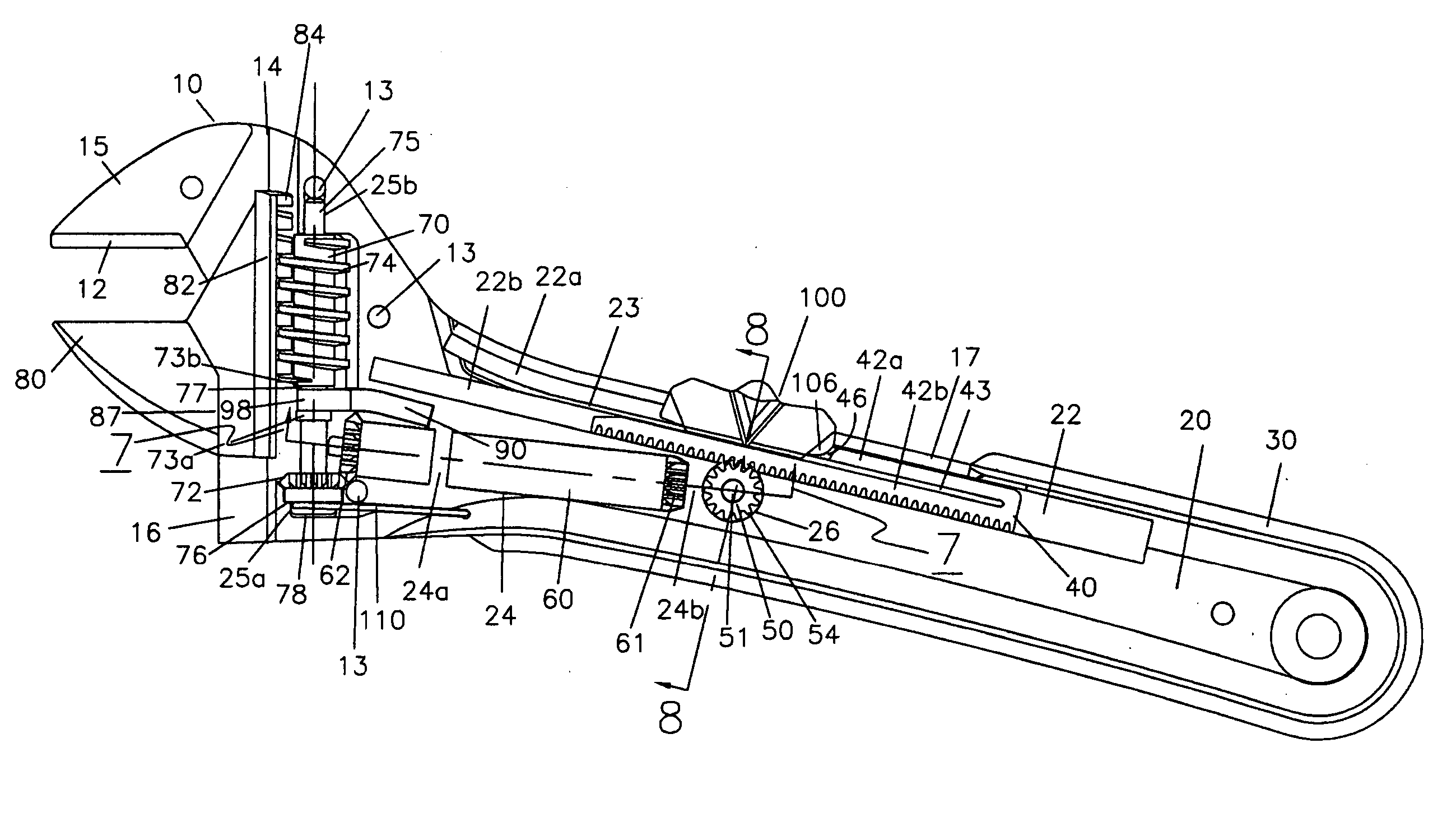
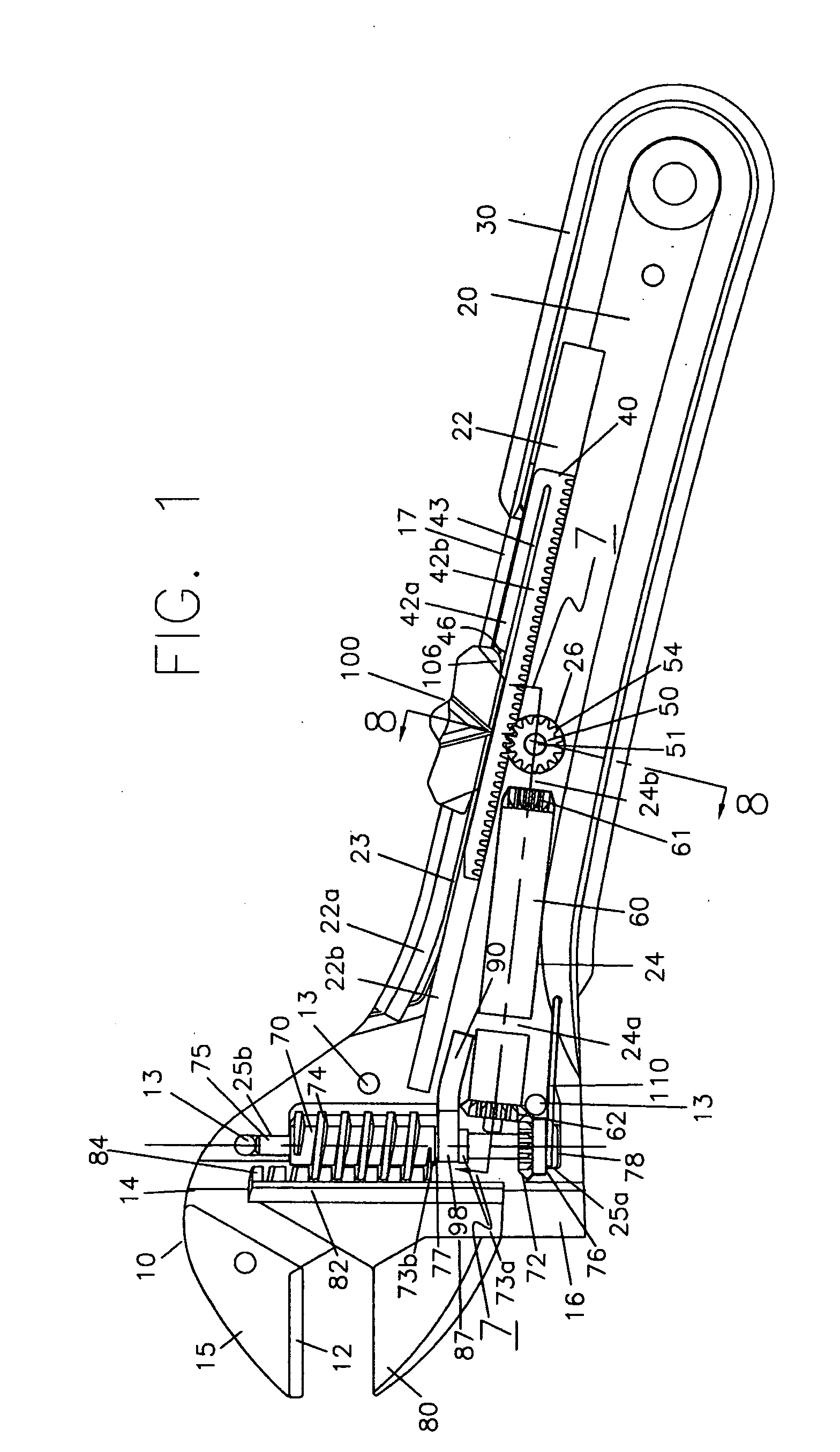
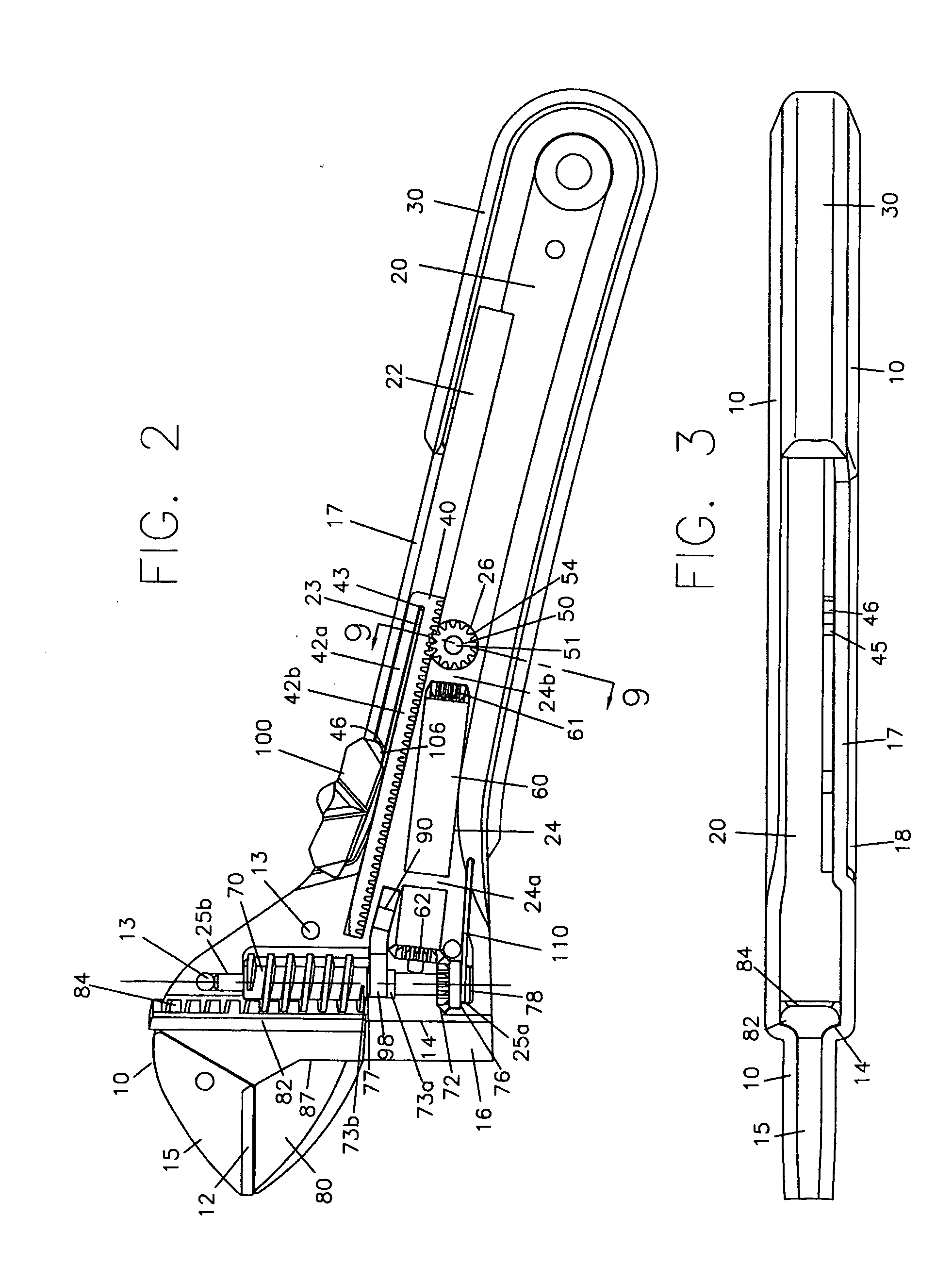
[0044] In a preferred embodiment of the present invention a series of rigid gears links a slide switch to a jaw holding worm gear. In FIG. 1 most of the essential elements of the wrench are visible. However FIGS. 8 and 9 show bevel gear portion 55 of pinion gear shaft 50. Moving slide switch 100 causes jaw 80 to move toward and away from the flange comprising fixed jaw face 12 of upper jaw insert 15 (FIG. 16). The flange may extend to cover the down facing metal edges of housing 10. Jaw insert 15 may be forged, machined or of powdered metal. In FIG. 1 switch 100 and jaw 80 are in an intermediate position. In FIG. 2 switch 100 has been pushed forward causing jaw 80 to close against face 12. Rack 40 is pivotably linked to switch 100 so that as switch 100 is moved, rack 40 moves with it. Switch 100 connects to rack 40 through notch 105 and tab 106 of the switch (FIG. 10). Specifically tab 106 extends into notch 46 (FIGS. 1,2, 11). Tab 45 forms the front limit of notch 46 in rack 40. Ra...


PUM


Abstract

A slide switch adjustable wrench uses a laminated steel construction method that includes a stepped surface to form a guide for the worm gear driven moving jaw. A molded or similarly formed body is sandwiched between the steel housing sides to form a sturdy structure. The body provides cavities, bearings and other features to support and guide moving parts within. A rack and pinion drive system uses simple molded gears to amplify about 2 inches of switch travel into about 6 turns of the worm gear. An overmolded rubber edge grip bonds to the body to create a recess in the body; this recess seamlessly fits the steel sides to form a smooth continuously contoured grip surface.

Description

FIELD OF THE INVENTION [0001] The present invention relates to wrenches. More precisely the present invention relates to a laminated steel plate method for construction of an adjustable wrench and similar tools. BACKGROUND OF THE INVENTION [0002] Adjustable jaw wrenches are well known. A movable jaw slides in a guide track, opposed to a fixed jaw, the jaws comprising an engaging end of the wrench. The guide track is cut in a solid formed housing, while the jaw is adjusted by means of a worm gear that is supported within the housing. Typically the worm gear functions as a thumb wheel wherein rotating the worm gear causes the jaw to move toward and away from the fixed jaw. An improvement to these devices has been to link the worm gear to a slide switch so that moving the switch causes the gear to rotate and the jaw to move. [0003] Two methods to link a sliding switch to a worm gear are typical of the prior art. According to one version, a sliding element links to a helical shaft so th...

Claims


Application Information

Patent Timeline
IPC IPC(8): B25B13/14B25B13/16
CPCB25B13/14
Inventor MARKS, JOELARLEEKUL, SURAPEN
Owner MARKS JOEL
Why Eureka
Try Eureka