Method and apparatus for reducing hot spot temperatures on stacked field windings

a technology of stacked field windings and windings, which is applied in the direction of windings, magnetic circuit rotating parts, magnetic circuit shapes/forms/construction, etc., can solve the problems of inability to reduce the heat generation rate of radial air cooling ducts that are machined in by punching operations, the limiting factor of increasing power density, and the inability to reduce the hot spot temperature. , to achieve the effect of reducing local hot spot temperatures and reducing heat generation ra

Inactive Publication Date: 2005-12-15
EL GABRY LAMYAA ABDEL ALLE +1
View PDF9 Cites 9 Cited by
  • Summary
  • Abstract
  • Description
  • Claims
  • Application Information

AI Technical Summary

Benefits of technology

[0010] The above discussed and other drawbacks and deficiencies are overcome or alleviated by a method and apparatus for reducing field hot spot temperatures through varying the copper turn thickness. More specifically, the concept being proposed capitalizes on the ability to reduce local hot spot temperature by reducing the local heat generation (i.e. by reducing the local resistance of the winding through increasing the copper cross-section area). Thus, in the broader aspects, the invention relates to an end turn arrangement for windings in a rotor where individual turns are stacked in parallel sided radial slots in the rotor, with successive turns having the same width in a radial inward direction, the end turns of the individual turns of each stack being aligned along both edges defining each slot, wherein the turn thickness is increased in regions of high temperature thereby reducing the temperature. An added benefit of having variable turn thickness is that it results in more uniform field temperatures which results in less thermal cycling, less fatigue, and longer part life as a result of the reduced temperature gradients between the field winding components.

Problems solved by technology

When the thickness increases, radial air cooling ducts that are machined in by a punch operation become increasingly more difficult to produce.
For example, conventional punch operations may produce an unacceptable bulge in a width dimension of the copper, and it is therefore necessary to create a ventilation scheme for the increasing cross sections of the copper windings without unacceptable bulges in the width dimension.
In many ventilated field windings, the hot spot temperature is the limiting factor in increasing power density.
The disadvantage of increasing flow is that it increases the pumping and windage losses which directly reduce generator efficiency.
Furthermore, tapered slots are more costly to machine than parallel slots and turns of variable width in a stack are more complex for manufacturers to make and assemble.

Method used


Image

  • Method and apparatus for reducing hot spot temperatures on stacked field windings
  • Method and apparatus for reducing hot spot temperatures on stacked field windings
  • Method and apparatus for reducing hot spot temperatures on stacked field windings

Examples


Embodiment Construction

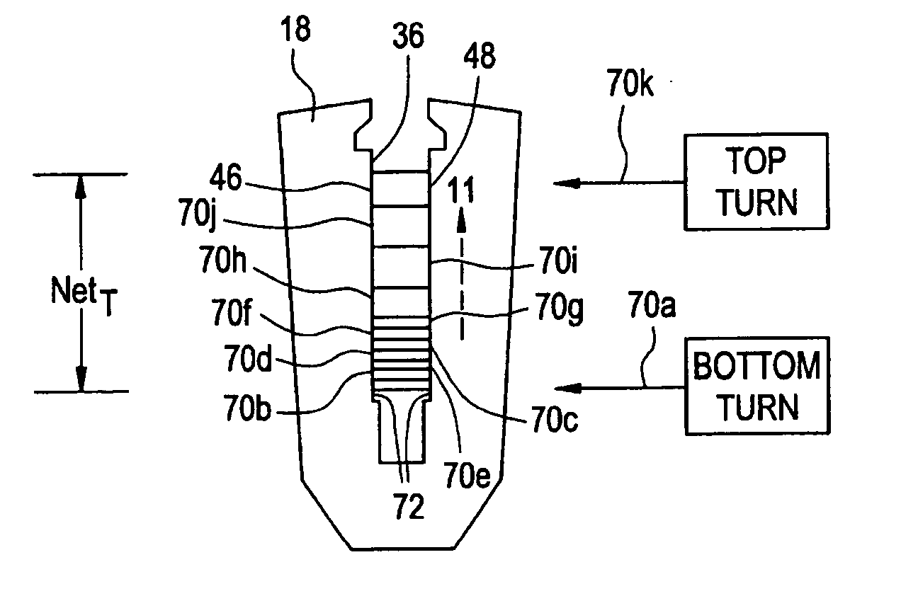
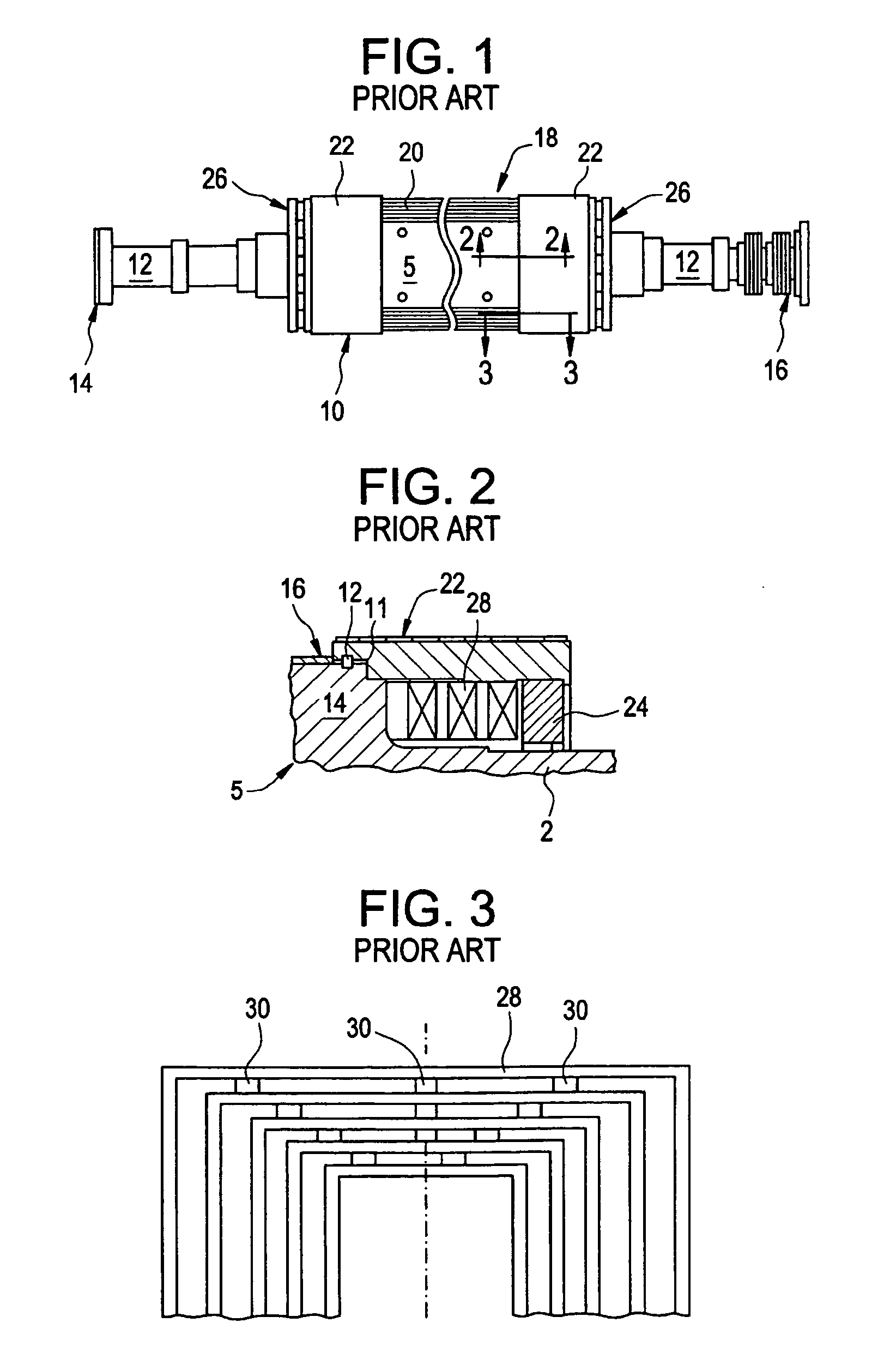
[0022]FIG. 1 illustrates a conventional rotor 10 for a generator (or motor). The rotor has a shaft 12 with a power turbine (or mechanical mode) coupling 14 and supported by bearings (not shown). The rotor shaft 12 also has a collector ring 16 that provides an electrical junction for the rotor field winding.

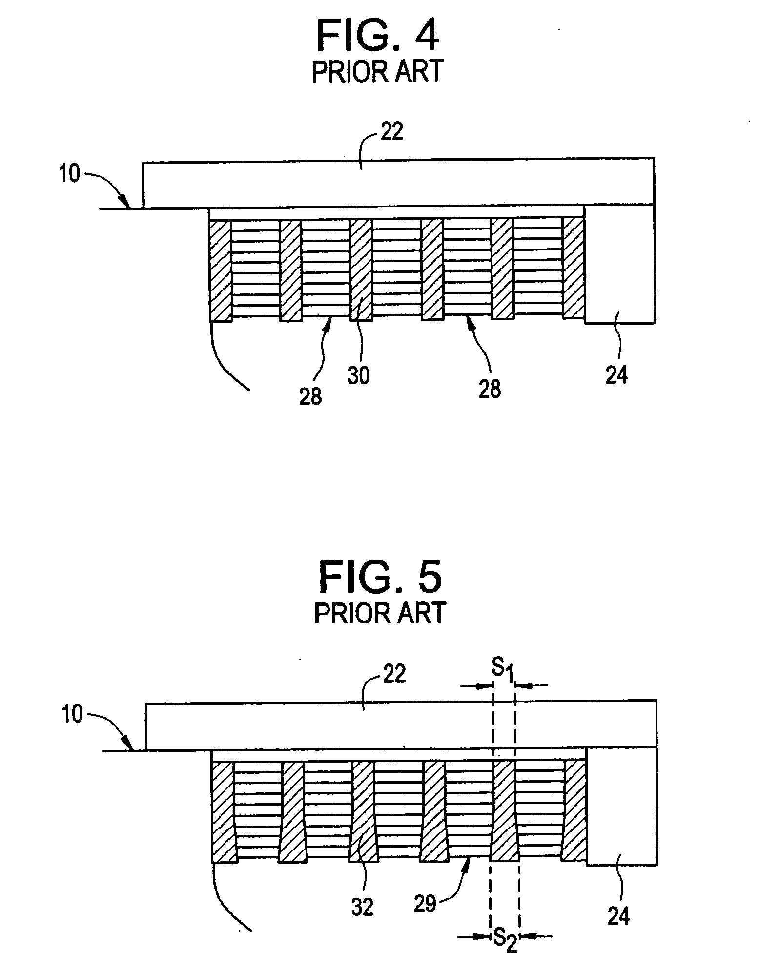
[0023] The rotor has a large diameter body 18 that holds the coil windings 20. The rotor body has longitudinally oriented slots extending radially outwardly from the center of the rotor 10, and in which the individual turns of the windings 20 are mounted. These slots extend the length of the rotor body, and annular retaining rings 22 cap both ends of the rotor body 18. The retaining rings are supported at one end by the rotor body (see FIG. 2). Adjacent the retaining rings 22 are fans 26 that cool the retaining rings and other rotor components.

[0024] As will be appreciated from FIG. 2, the retaining rings 22 slide over the end of the rotor body 18 and are attached to the rotor b...


PUM


Abstract

A method and apparatus for a generator coil includes a plurality of stacked windings in a rotor where individual turns are stacked in parallel sided radial slots in the rotor. Each successive turn has the same width substantially corresponding to a constant width of each slot, wherein a first turn has a first thickness and a second turn has a second thickness thicker than said first thickness. The second turn is employed in regions of high temperature thereby reducing the temperature thereof.

Description

CROSS REFERENCE TO RELATED APPLICATIONS [0001] This application is a divisional application of U.S. patent application Ser. No. 10 / 707,911, filed on Jan. 23, 2004, the disclosure of which is herein incorporated by reference in its entirety.BACKGROUND OF THE INVENTION [0002] This invention relates generally to generator field windings and, more specifically, to generator field windings configured and disposed on a generator rotor in a manner to reduce hot spot temperatures. [0003] Generator rotors are provided with radial slots about the periphery thereof, for receiving field or rotor windings of coils made up of a number of turns in a radially stacked arrangement, each turn or winding separated by insulation. The windings are retained in the slots by full-length wedges, with creepage blocks interposed between the wedges and the windings. [0004] Generators currently available from the assignee of the present application are placed in three major design classifications based on the co...

Claims


Application Information

Patent Timeline
Patent Type & Authority Applications(United States)
IPC IPC(8): H02K3/12H02K9/00H02K3/24
CPCH02K3/12H02K9/00Y10T29/49073
Inventor EL-GABRY, LAMYAA ABDEL-ALLEJONES, STEVEN WILLIAM
Owner EL GABRY LAMYAA ABDEL ALLE
Why Eureka
Try Eureka