Supercharge Your Innovation With Domain-Expert AI Agents!

Hall sensor alignment for BLDC motor

a bldc motor and sensor technology, applied in the direction of motor/generator/converter stopper, electronic commutator, dynamo-electric converter control, etc., can solve the problem of generating lower torque at a given current, the position measured by the hall sensor may not exactly match the real rotor position, and the introduction of errors

Active Publication Date: 2005-12-15
INFINEON TECH AMERICAS CORP
View PDF30 Cites 38 Cited by
  • Summary
  • Abstract
  • Description
  • Claims
  • Application Information

AI Technical Summary

Benefits of technology

[0004] To address and avoid these potential sources of error, a technique has been developed to determine an alignment error of a Hall sensor location in a brushless DC motor drive, by measuring the back EMF waveform preferably while the motor is coasting.
[0005] The technique is characterized in that an angular offset is calculated between a selected BEMF wa...

Problems solved by technology

Errors are introduced due to the relative mechanical locations of the Hall sensor and the magnet, the resolution and accuracy of the sensor, the pole width of the sense magnet, and the physical relationship between the sense magnet and the rotor.
Because of these potential sources of error, the position measured by the Hall sensors may not exactly match the real rotor position.
This position error can cause generation of lower torque at a given current.

Method used


Image

  • Hall sensor alignment for BLDC motor
  • Hall sensor alignment for BLDC motor
  • Hall sensor alignment for BLDC motor

Examples


Embodiment Construction

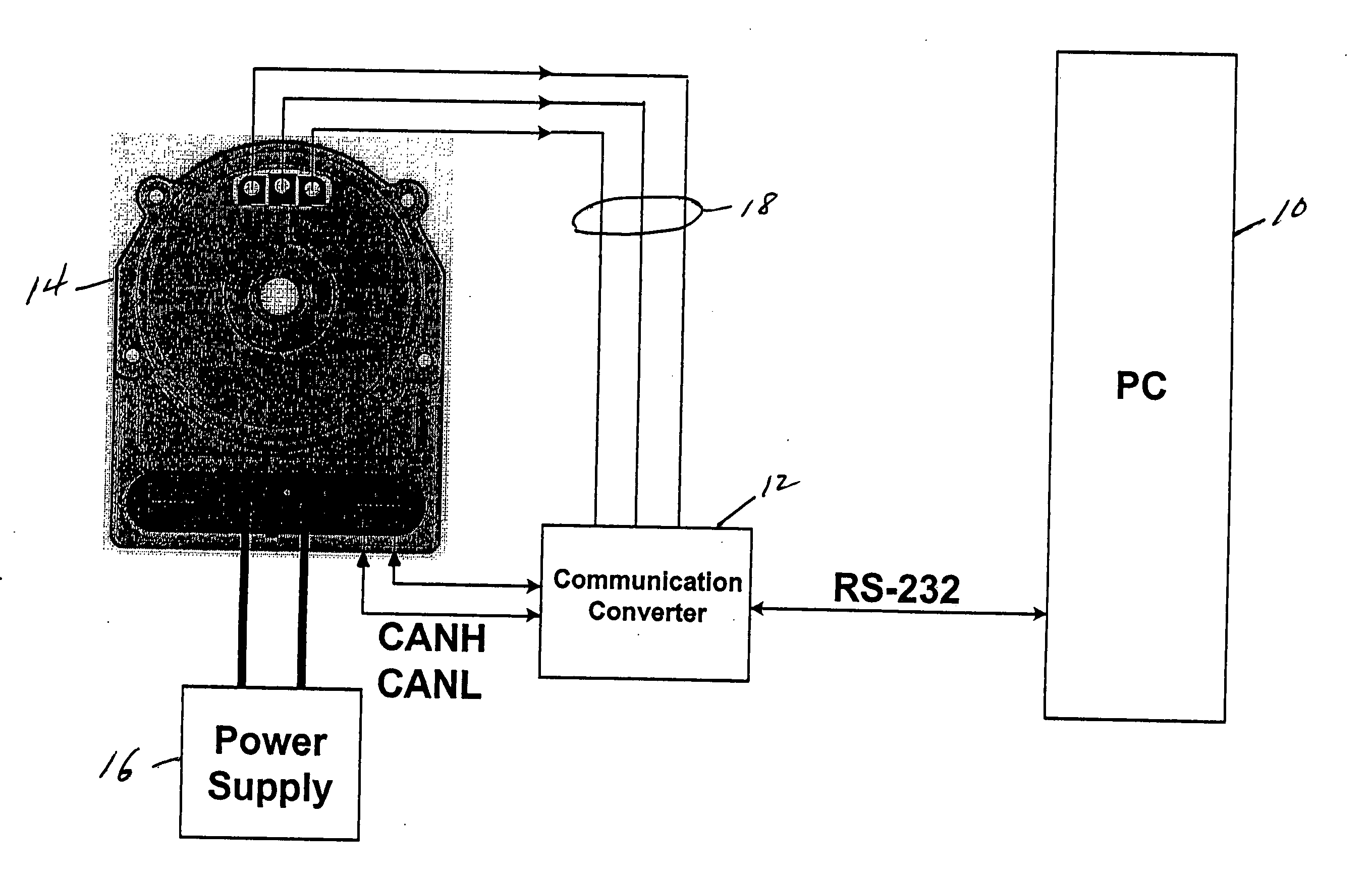
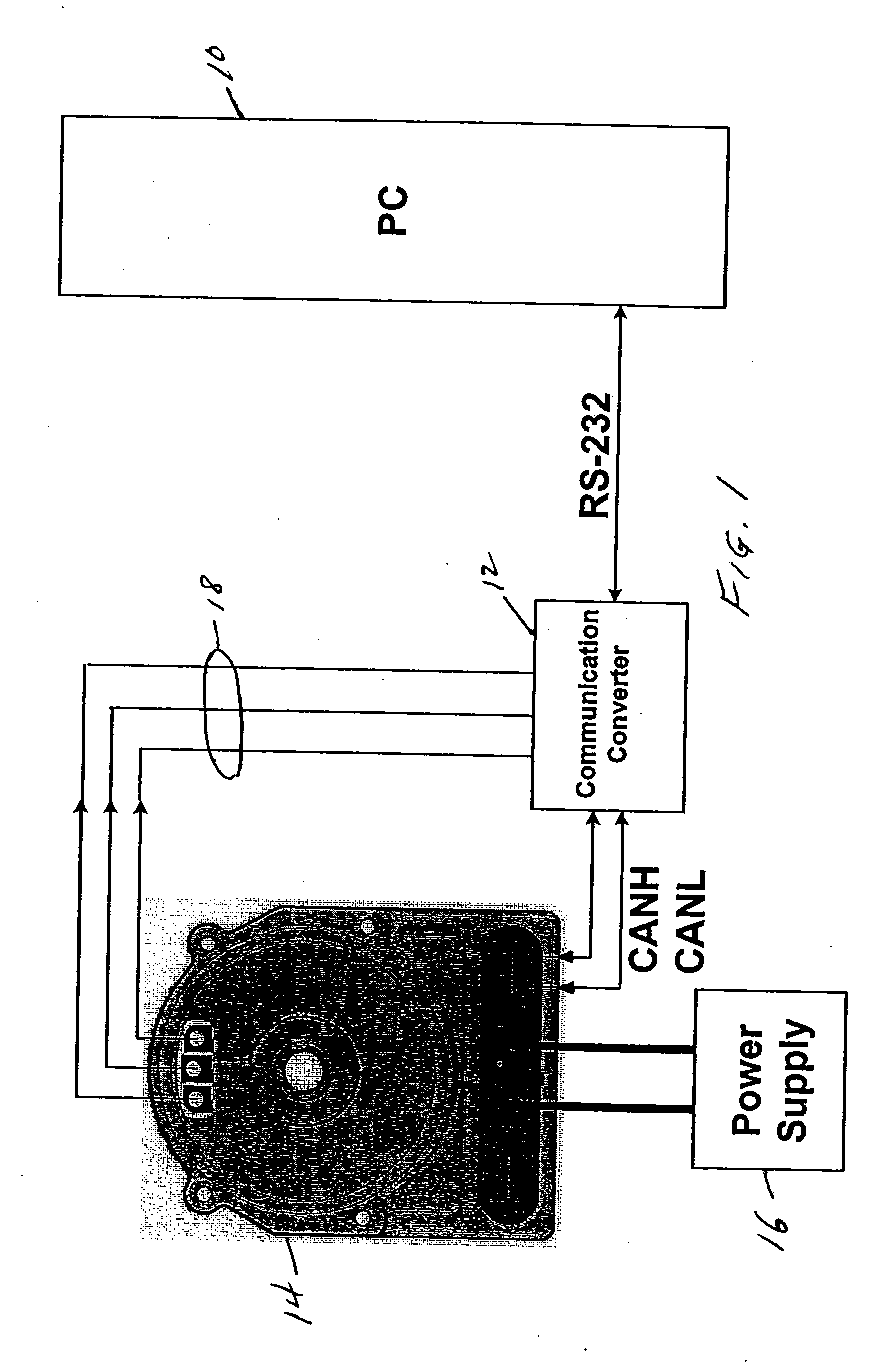
[0015] A technique has been developed whereby an external unit which can control the BLDC motor under test, and which has electrical access to the motor phase voltages, can measure and indicate how to correct the Hall alignment.

[0016] An example of such an arrangement is shown in FIG. 1, comprising a PC 10, a communication converter 12, a motor with an electronic control unit (ECU) 14 and a power supply 16. In an example of a test procedure, the PC controls the communication converter to start Hall alignment. The communication converter controls the ECU to run the motor at a selected speed and to enter Hall alignment mode. Then the ECU stops the motor drive, allowing the motor to coast, and the communication converter begins sensing the Hall and BEMF signals over the lines 18 and the lines CANH / CANL. The communication converter calculates a phase advance if needed to correct a Hall alignment error and controls the ECU to store such phase advance in an EEPROM, for example, for use i...


PUM


Abstract

A technique for determining an alignment error of a Hall sensor location in a brushless DC motor drive, by measuring the back EMF waveform, preferably while the motor is coasting. According to the technique, an angular offset is calculated between a selected BEMF waveform and a selected Hall signal. Such offsets are preferably calculated for each phase individually. The offsets may be advantageously stored in the motor control unit and used to adjust the output motor control signals for maximum torque.

Description

CROSS REFERENCE TO RELATED APPLICATION [0001] The present application is based upon and claims priority of U.S. Provisional Application Ser. No. 60 / 579,037 filed Jun. 11, 2004, incorporated by reference in its entirety.BACKGROUND OF THE INVENTION [0002] The present invention relates to a brushless DC motor drive, and more particularly to a method and system for determining an alignment error of a Hall sensor in such a drive, advantageously for optimizing the location of the Hall sensor. [0003] Brushless DC motor drives commonly use Hall-effect sensors to determine rotor position. The Hall sensors sense the magnetic field of a magnet on the rotor, and produce a digital pattern indicating the rotor position in one of 6 possible sectors. Errors are introduced due to the relative mechanical locations of the Hall sensor and the magnet, the resolution and accuracy of the sensor, the pole width of the sense magnet, and the physical relationship between the sense magnet and the rotor. Becau...

Claims


Application Information

Patent Timeline
IPC IPC(8): H02P7/06
CPCH02P6/16H02P6/182H02P6/15
Inventor BOLT, LAIRD
Owner INFINEON TECH AMERICAS CORP
Features
  • R&D
  • Intellectual Property
  • Life Sciences
  • Materials
  • Tech Scout
  • Unparalleled Data Quality
  • Higher Quality Content
  • 60% Fewer Hallucinations
Learn More