
Method and control device for operating a magnetic resonance tomography apparatus to select appropriate local coils

Inactive Publication Date: 2005-12-15
SIEMENS HEALTHCARE GMBH
View PDF8 Cites 37 Cited by
  • Summary
  • Abstract
  • Description
  • Claims
  • Application Information

AI Technical Summary

Benefits of technology

[0019] Additionally or alternatively, an absolute minimum value, or a combination of a threshold that is a relative fraction of the maximal measured intensity value and an absolute minimum value can be selected. This has the advantage of ensuring that an adequate signal is measured with the coils selected for the magnitude measurement.
[0021] This means that an intersection of the respective three-dimensional exposure profile with the region to be examined is determined, for example a specific slice, a slice stack, a specific volume, a region of interest (ROI) etc. Given known coil positions that can be established using the measured signal intensity distribution and with the aid of the binary exposure profile generated from the signal intensity distribution, the determination of such slice regions can be implemented fully automatically, quickly and simply.

Problems solved by technology

The correct selection of the coils thus requires a significant degree of knowledge and experience on the part of the operator, particularly since the available information specified at the factory about positions and exposure regions of the coils is often not sufficiently precise in practice and does not take into account the real factors for the actual measurement.
Insofar as the optimal coil or coil combination is not selected for a subsequent measurement, the quality of the subsequent exposures is also unavoidably worsened.
This can possibly lead to scans having to be repeated, which extends the total exposure time.
This not only reduces the efficiency of the magnetic resonance tomography apparatus and of the operating personnel, but also most notably leads to a higher exposure of the patient.

Method used


Image

  • Method and control device for operating a magnetic resonance tomography apparatus to select appropriate local coils
  • Method and control device for operating a magnetic resonance tomography apparatus to select appropriate local coils
  • Method and control device for operating a magnetic resonance tomography apparatus to select appropriate local coils

Examples


Embodiment Construction

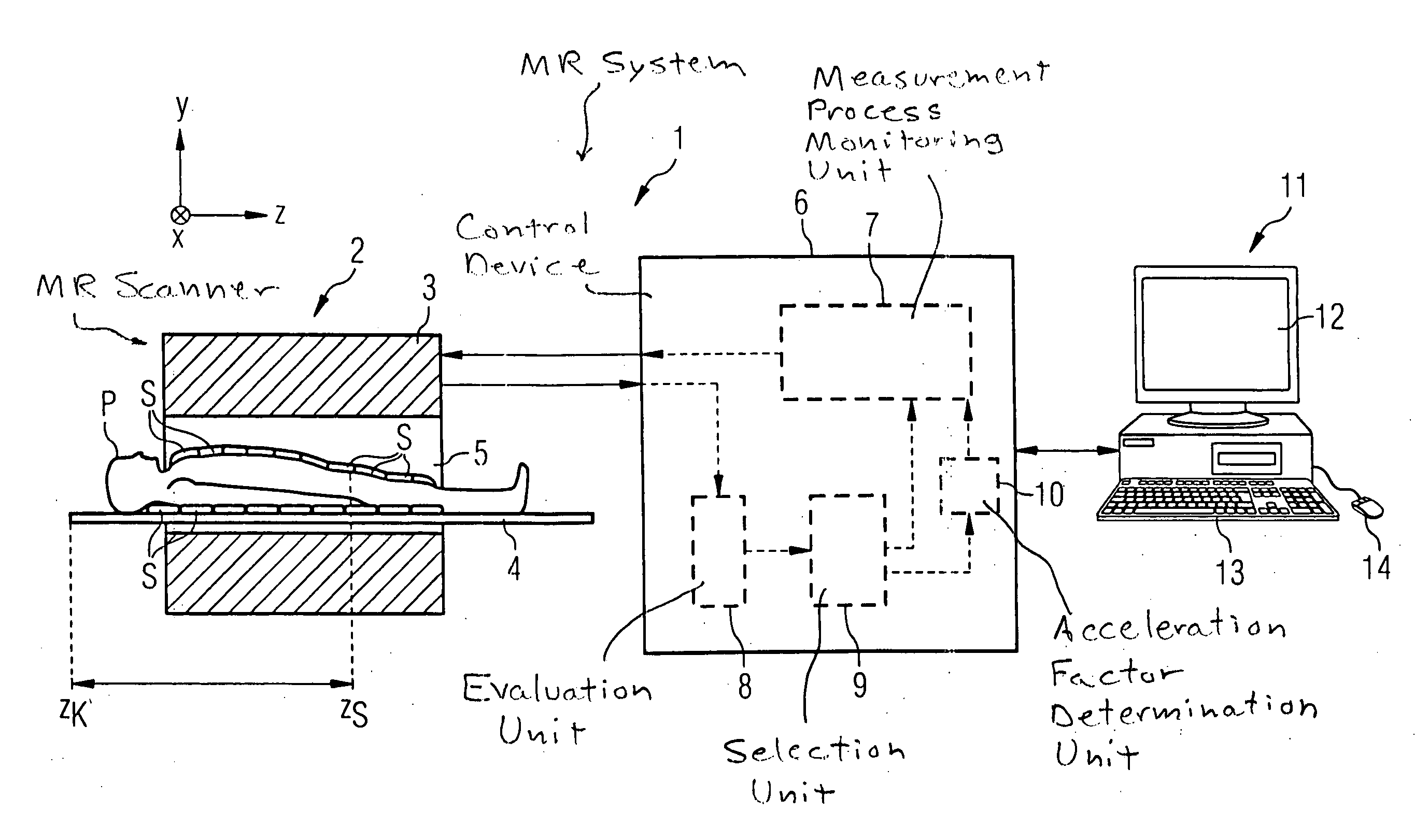
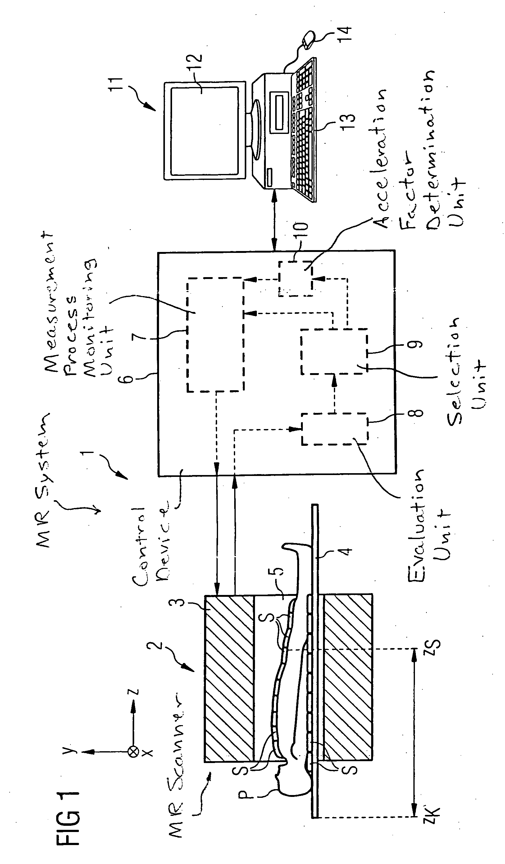
[0043]FIG. 1 shows an exemplary embodiment for a magnetic resonance system 1 that is operable according to the inventive method. The core of this magnetic resonance system 1 is the magnetic resonance scanner 2, in which a patient P is positioned on a patient positioning table 4 (also called a recumbent board 4) in an annular basic field magnet 3 that surrounds the measurement volume 5. A number of local coils S are located on and possibly also under the patient.

[0044] The table 4 can be moved in the longitudinal direction, i.e. along the longitudinal axis of the scanner 2. This direction is designated as the z-direction in the indicated spatial coordinate system (likewise shown). A whole-body coil (not shown in detail) with which radio-frequency pulses can be emitted and received is located within the basic field magnet in the scanner 2. Moreover, in a typical manner (not shown in Figure), the scanner 2 has gradient coils in order to be able to apply a magnetic field gradient in ea...


PUM


Abstract

In a method for generation of magnetic resonance exposures and a control device for a magnetic resonance tomography apparatus, a number of coils are available in the apparatus, the coils being are positioned at various locations relative to the examination subject. Initially a radio-frequency signal is emitted and a spatially-resolved signal intensity distribution is measured with at least one or some of the available coils. An automatic determination of a three-dimensional exposure profile of the appertaining coils is made based on the received signals. A selection of one or more of the appertaining coils for a subsequent magnetic resonance measurement is made on the basis of the determined exposure profiles of the coils as well as the measurement region to be acquired in the magnetic resonance measurement.

Description

BACKGROUND OF THE INVENTION [0001] 1. Field of the Invention [0002] The present invention concerns a method for generation of magnetic resonance exposures of an examination subject, wherein a number of coils that are positioned at various locations relative to the examination subject are available in the magnetic resonance tomography apparatus that is used. Moreover, the invention concerns a corresponding control device for a magnetic resonance tomograph in order to generate magnetic resonance exposures of an examination subject according to such a method as well as a magnetic resonance tomography apparatus with such a control device. [0003] 2. Description of the Prior Art [0004] Modern magnetic resonance (MR) systems normally operate with a number of various antennas (called coils in the following) for emission of radio-frequency pulses for nuclear magnetic resonance excitation and / or for receipt of the induced magnetic resonance signals. A magnetic resonance system normally has a ...

Claims


Application Information

Patent Timeline
IPC IPC(8): G01R33/483G01V3/00G01R33/3415
CPCG01R33/3415
Inventor CAMPAGNA, SWEN
Owner SIEMENS HEALTHCARE GMBH
Learn More