Microstrip stack patch antenna using multilayered metallic disk array and planar array antenna using the same

a multi-layer metallic disk array and patch antenna technology, applied in individual energised antenna arrays, resonant antennas, antenna earthings, etc., can solve the problems of narrow operation band, decreased antenna efficiency, complicated feed network, etc., and achieve the effect of improving side lobe and gain characteristics

Inactive Publication Date: 2005-12-15
ELECTRONICS & TELECOMM RES INST
View PDF6 Cites 16 Cited by
  • Summary
  • Abstract
  • Description
  • Claims
  • Application Information

AI Technical Summary

Benefits of technology

[0025] In accordance with an aspect of the present invention, there is provided a microstrip stack patch antenna, which includes: a microstrip stack patch including feed line and a pa

Problems solved by technology

As a result, the feed network becomes complicated.
Also, due to the loss caused by the mutual coupling effect between the radiating element and the feed line and the loss caused by a long feed line, the antenna efficiency is decreased.
However, it has a disadvantage

Method used


Image

  • Microstrip stack patch antenna using multilayered metallic disk array and planar array antenna using the same
  • Microstrip stack patch antenna using multilayered metallic disk array and planar array antenna using the same
  • Microstrip stack patch antenna using multilayered metallic disk array and planar array antenna using the same

Examples


Embodiment Construction

[0040] Other objects and aspects of the invention will become apparent from the following description of the embodiments with reference to the accompanying drawings. Thus, those skilled in the art can easily embody the technological concept of the present invention. If any detailed description on a widely known technology in relation to the present invention is determined to blur the point of the present invention, it will be omitted. Hereinafter, preferred embodiments of the present invention will be described with reference to accompanying drawings.

[0041] In the present invention, it is assumed that a dielectric material used in a dielectric foam layer has nearly an ideal dielectric constant, i.e., ε=1.05, and the thin thickness of a dielectric film is neglected.

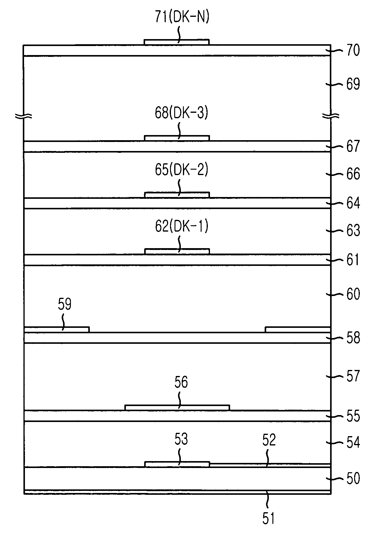
[0042]FIG. 5A is a cross-sectional diagram illustrating a microstrip stack patch antenna using a multilayered metallic disk array in accordance with an embodiment of the present invention, and FIG. 5B presents a top view...


PUM


Abstract

Provided are a microstrip stack patch antenna using multilayered metallic disk array and a planar array antenna using the same. The microstrip stack patch antenna of the present research concentrates beam patterns and acquires a high gain characteristic by finitely depositing metallic disks in a bore-sight on a conventional microstrip stack patch radiator. The microstrip stack patch antenna includes: a microstrip stack patch directly connected to the feed line; and a mask conductor layer for improving side lobe and gain characteristics, the mask conductor being formed on the microstrip stack patch.

Description

FIELD OF THE INVENTION [0001] The present invention relates to a microstrip stack patch antenna using a multilayered metallic disk array; and, more particularly, to a microstrip stack patch antenna using a multilayered metallic disk array which has a concentrated beam pattern and a high gain property by depositing metallic disks on the microstrip stack patch radiator in a direction that electromagnetic waves are propagated, and a planar array antenna using the same. DESCRIPTION OF RELATED ART [0002] Generally, medium and long-range communication / broadcasting application fields, such as Wireless Local Area Network (WLAN) antenna, and satellite broadcast receiving antenna, require a high-gain and broadband planar array antenna. [0003] Generally, the planar array antenna can obtain a required level of gain by increasing the number of radiating elements. According to the method, however, if the gain of a radiating element is low, the array space between radiating elements is narrow and ...

Claims


Application Information

Patent Timeline
IPC IPC(8): H01Q1/22H01Q13/08H01Q1/38H01Q9/04H01Q21/06
CPCH01Q1/22H01Q9/0414H01Q1/38H01Q13/08H01Q21/065
Inventor EOM, SOON-YOUNGJEON, SOON-IKKIM, CHANG-JOO
Owner ELECTRONICS & TELECOMM RES INST
Why Eureka
Try Eureka