
Wireless flow measurement in arterial stent

a technology of flow measurement and arterial stent, which is applied in the field of flow sensing devices and techniques, can solve the problems of ventricular tachycardia, particularly serious problems, and procedures that are typically extremely invasive or unreliable, and achieve the effects of preventing ventricular tachycardia from developing

Inactive Publication Date: 2005-12-15
HONEYWELL INT INC
View PDF31 Cites 123 Cited by
  • Summary
  • Abstract
  • Description
  • Claims
  • Application Information

AI Technical Summary

Benefits of technology

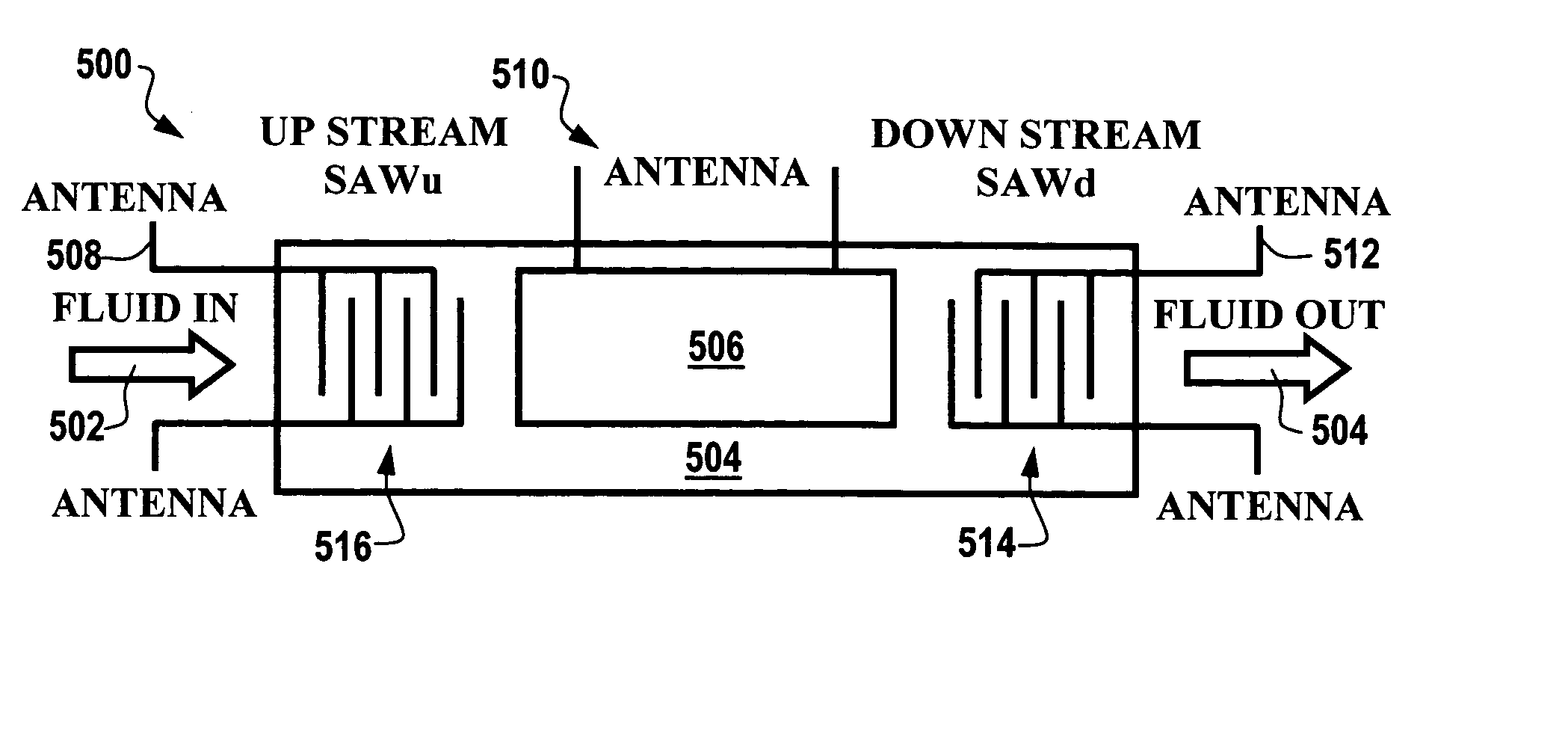
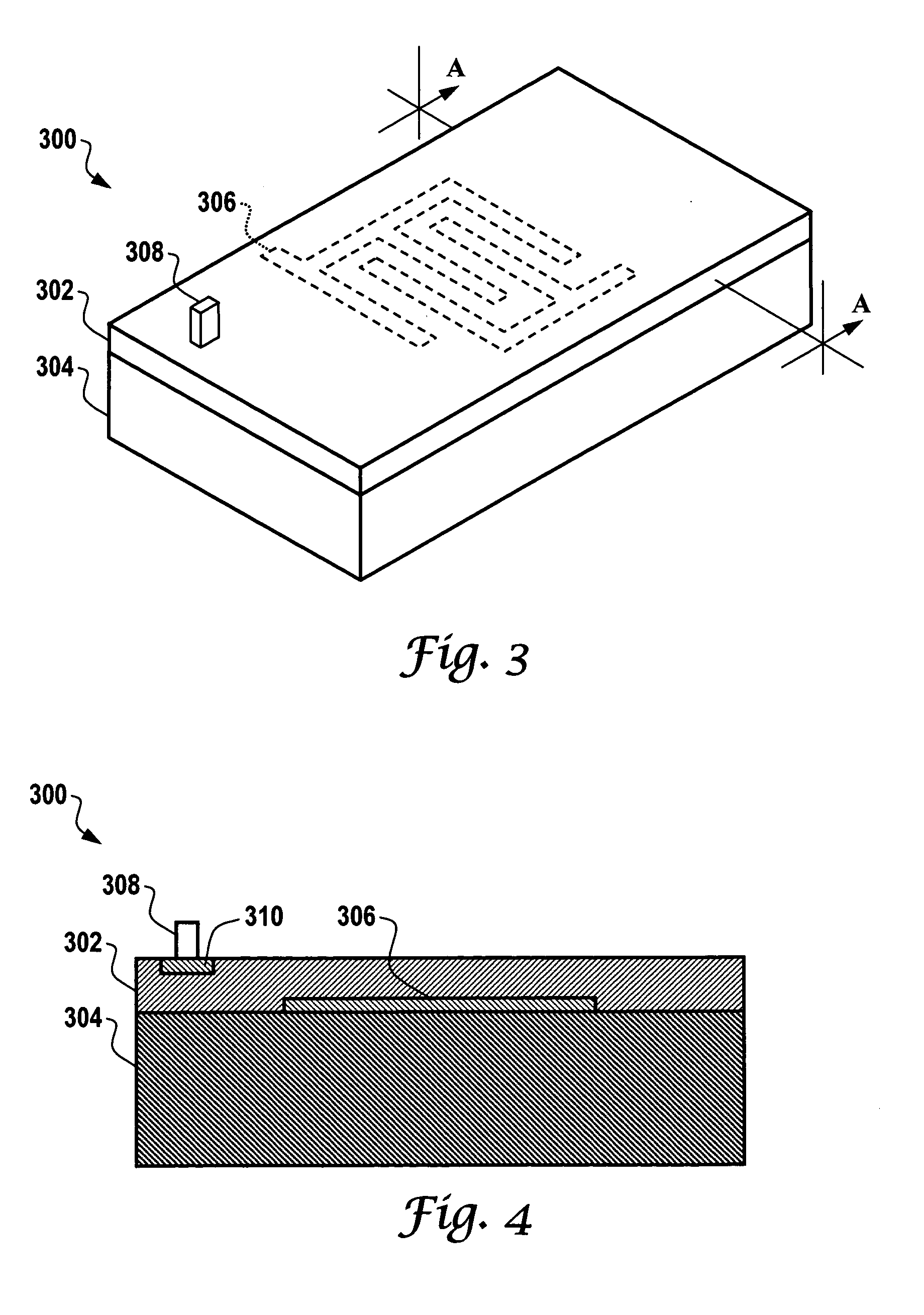
The present invention provides improved blood flow sensor devices and sensing techniques. It offers an interdigital surface wave device, such as a surface acoustic wave (SAW) resonator or delay line sensing device, which can be adapted for use in blood flow sensing applications. It also provides a wireless blood flow sensor that can be integrated with a stent used in medical procedures, for blood flow sensing activities thereof. The sensor measures the flow of blood within a blood vessel when stimulated with a short range radio frequency energy field detectable by an antenna. The system includes a transmitter and receiver unit that transmits and receives data transmitted from the sensor via the antenna. The sensor can also incorporate pressure and temperature sensing elements. The stent integrated with the sensor provides a rigid support for holding the blood vessel open in order to measure the flow of blood within the blood vessel.

Problems solved by technology

Ventricular tachycardia presents a particularly serious problem because the patient, if left untreated, may progress into ventricular fibrillation.
Such procedures are typically extremely invasive or can be unreliable.
Blood vessels, for example, can become obstructed due to plaque or tumors that restrict the passage of blood.
To date such devices have not been incorporated successfully into medical applications, particularly those involving the use of stents.

Method used


Image

  • Wireless flow measurement in arterial stent
  • Wireless flow measurement in arterial stent
  • Wireless flow measurement in arterial stent

Examples


Embodiment Construction

[0038] The particular values and configurations discussed in these non-limiting examples can be varied and are cited merely to illustrate at least one embodiment of the present invention and are not intended to limit the scope of the invention.

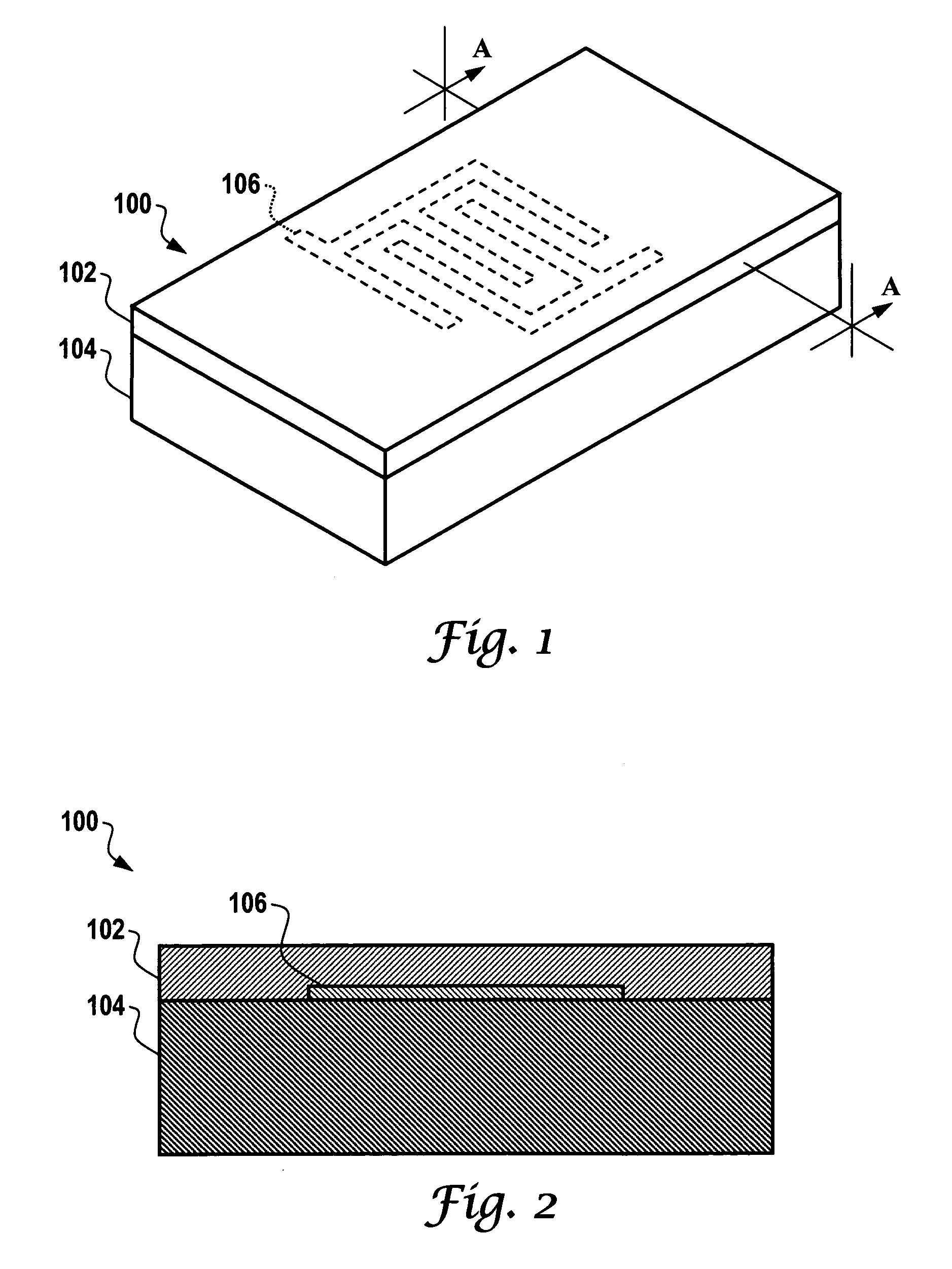
[0039]FIG. 1 illustrates a perspective view of an interdigital surface wave device 100, which can be implemented in accordance with one embodiment of the present invention. Surface wave device 100 can be adapted for use in blood flow sensing activities, as described in further detail herein. Surface wave device 100 can be configured to generally include an interdigital transducer 106 formed on a piezoelectric substrate 104. The surface wave device 100 can be implemented in the context of a sensor chip. Interdigital transducer 106 can be configured in the form of an electrode.

[0040]FIG. 2 illustrates a cross-sectional view along line A-A of the interdigital surface wave device 100 depicted in FIG. 1, in accordance with one embodiment of the p...


PUM


Abstract

A blood flow sensing system is disclosed, including a sensor coupled to an antenna, such that the sensor measures a flow of blood within a blood vessel when stimulated with a short range radio frequency energy field detectable by the antenna. Such a system additionally can include a transmitter and receiver unit (i.e., a transmitter / receiver), which can transmit the short range radio frequency energy field to the antenna of the sensor. The transmitter and receiver unit can also receive data transmitted from the sensor via the antenna. Such a system additionally includes a stent integrated with sensor, wherein the stent comprises a small diameter cylinder that props open a blood vessel and wherein the stent is moveable into the blood vessel to form a rigid support for holding the blood vessel open in order to measure the flow of blood within the blood vessel.

Description

TECHNICAL FIELD [0001] Embodiments are generally related to flow sensing devices and techniques. Embodiments are also related to stents, such as, for example, arterial stents utilized in medical procedures. Embodiments are also related to surface wave sensor devices and systems, including interdigital sensors. BACKGROUND OF THE INVENTION [0002] Cardiac output or blood flow is one of the key indicators of the performance of the heart. Blood flow can be defined as volume of blood or fluid flow per time interval. Fluid or fluid velocity is generally a function of flow area at the measurement site. Use of blood flow measurements allows discrimination between physiologic rhythms, such as sinus tachycardia, which is caused by exercise or an emotional response, and other pathologic rhythms, such as ventricular tachycardia or ventricular fibrillation. [0003] Cardiac arrhythmia is defined as a variation of the rhythm of the heart from normal. The cardiac heartbeat normally is initiated at th...

Claims


Application Information

Patent Timeline
Patent Type & Authority Applications(United States)
IPC IPC(8): A61B5/00A61B5/02A61B5/026
CPCA61B5/0031A61B5/026A61B5/6876A61B5/6862A61B5/411
Inventor ALDERMAN, RICHARD A.GONIA, PATRICK S.LIU, JAMES Z.
Owner HONEYWELL INT INC
Learn More