Meniscus prosthesis

a meniscus and prosthesis technology, applied in the field of meniscus prosthesis, can solve the problems of limited healing ability of damaged articular cartilage, limited mobility, severe pain,

a meniscus and prosthesis technology, applied in the field of meniscus prosthesis, can solve the problems of limited healing ability of damaged articular cartilage, limited mobility, severe pain,

US20050278025A1Inactive Publication Date: 2005-12-15CARTIVA INC

Image

  • Meniscus prosthesis
  • Meniscus prosthesis
  • Meniscus prosthesis

Examples


Embodiment Construction

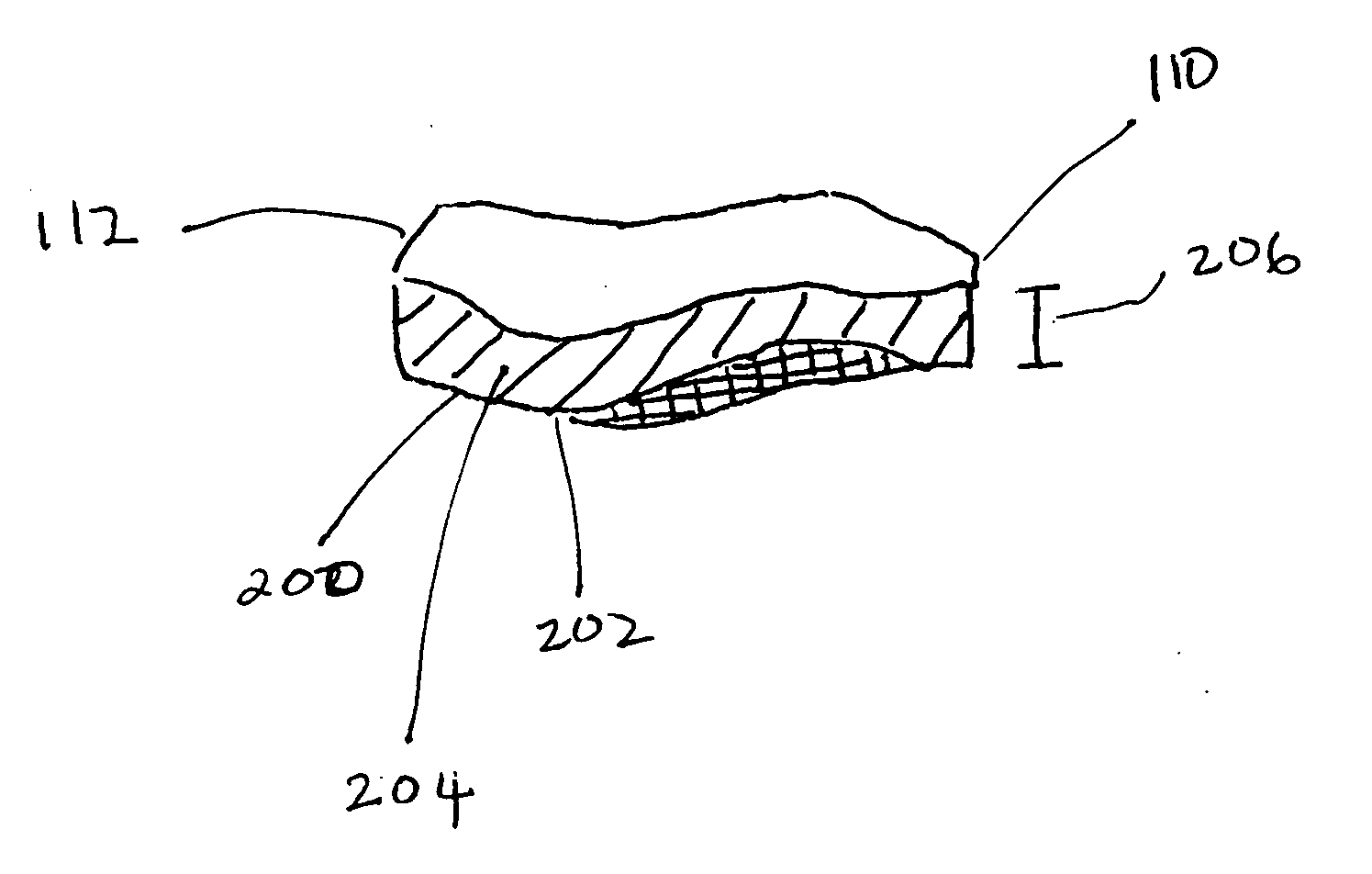
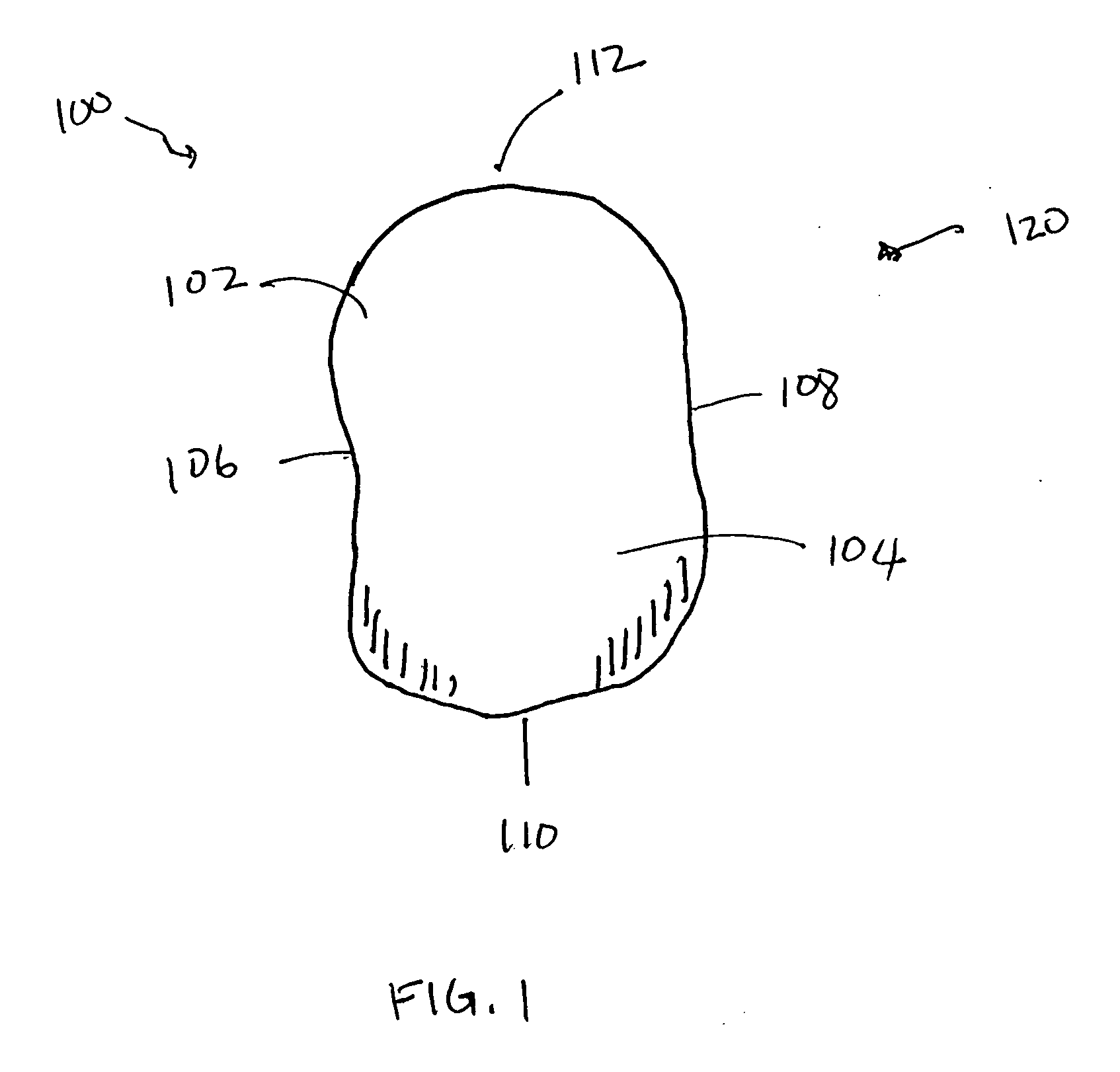
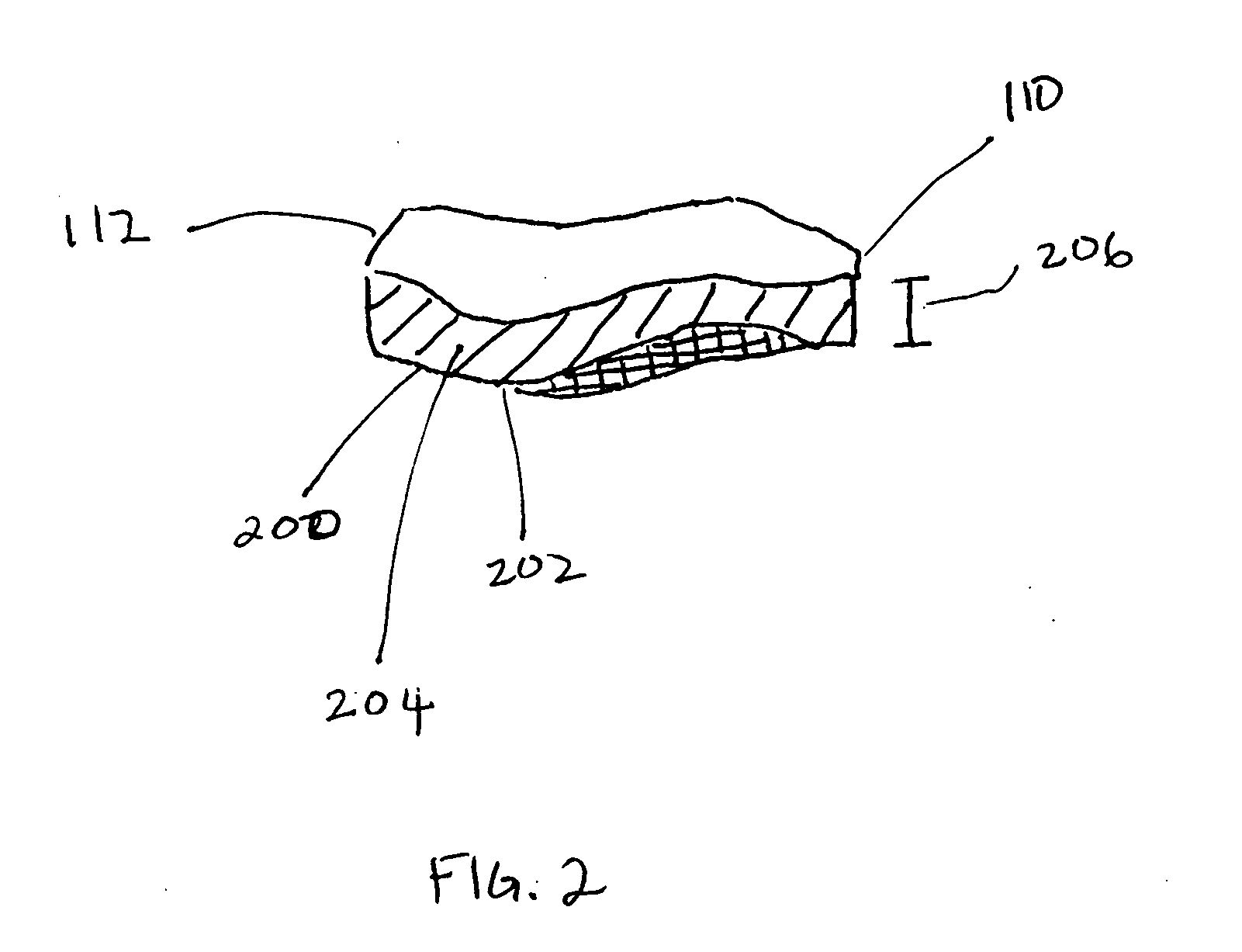
[0015] The present device provides an alternative for those situations in which cartilage degeneration and destruction is present in a single joint compartment. It is an intermediate treatment modality positioned between cartilage repair methods and knee arthroplasty. Rather than debriding soft tissue (menisectomy) or removing and replacing unaffected bone and cartilage (joint replacement), this surgical treatment places a cushioning “spacer” disk into the joint space above the tibial plateau. The device can be placed into the joint space above the tibial plateau. The femur, tubercle, and tibial plateau then articulate against the surface of the device. The device is shaped to conform to the femoral condyle on its superior surface and the tubercle and tibial plateau on its inferior surface and joint capsule on its periphery. The geometric shape of the device further allows for articulation with the femoral condyle, tubercle, and the tibial plateau while keeping the prosthesis in pla...


PUM


Abstract

A prosthesis for placement into a joint space between two or more bones is disclosed. The prosthesis includes a body formed from a pre-formed solid one piece elastomer, wherein the elastomer is formed from a synthetic organic polymer that is biocompatible and has a modulus of elasticity and a mechanical strength between 0.5 MPa and 75 MPa. The body having a shape contoured to fit within a joint space between the femoral condyle, tubercle, and tibial plateau without any means of attachment.

Description

BACKGROUND OF THE INVENTION [0001] Cartilage may be damaged by direct contact injury, inflammation or most commonly, by osteoarthritis (OA). Osteoarthritis, a process not completely understood by scientists, is the tissue degeneration process that can accompany daily cartilage wear. [0002] Damaged articular cartilage has limited ability to heal due to lack of a direct blood supply. After OA starts, the body can do little by itself to stop tissue deterioration. The injured cartilage goes through a staged degradation process in which the surface softens, flakes and fragments. Finally, the entire cartilage layer is lost and the underlying subchondral bone is exposed. During the early stages, OA symptoms may include stiffness, aching joints and deformity (axial malignment). Because the cartilage layer lacks nerve fibers, patients are often unaware of the severity of the damage. During the final stage, an affected joint consists of bone rubbing against bone, which leads to severe pain an...

Claims


Application Information

Patent Timeline
15 Dec 2005
Publication
US20050278025A1
IPC
A61F2/00; A61F2/30; A61F2/38; A61F2/40; A61F2/42
CPC
A61F2/30965; A61F2250/0084; A61F2/3872; A61F2/40; A61F2/4202; A61F2002/30069; A61F2002/30131; A61F2002/30133
Inventors
KU, DAVID N.; MEYER, RALPH A.