Methods of scanning an object that includes multiple regions of interest using an array of scanning beams

Active Publication Date: 2005-12-22
APPL MATERIALS ISRAEL LTD
View PDF5 Cites 25 Cited by
  • Summary
  • Abstract
  • Description
  • Claims
  • Application Information

AI Technical Summary

Benefits of technology

[0013] Conveniently, the aggregate area of the multiple regions of interest is relatively small in relation to the size of a sur

Problems solved by technology

The relative size difference between wafers size and the be

Method used


Image

  • Methods of scanning an object that includes multiple regions of interest using an array of scanning beams
  • Methods of scanning an object that includes multiple regions of interest using an array of scanning beams
  • Methods of scanning an object that includes multiple regions of interest using an array of scanning beams

Examples


Example

[0023] In the following detailed description of the preferred embodiments and other embodiments of the invention, reference is made to the accompanying drawings. It is to be understood that those of skill in the art will readily see other embodiments and changes may be made without departing from the scope of the invention.

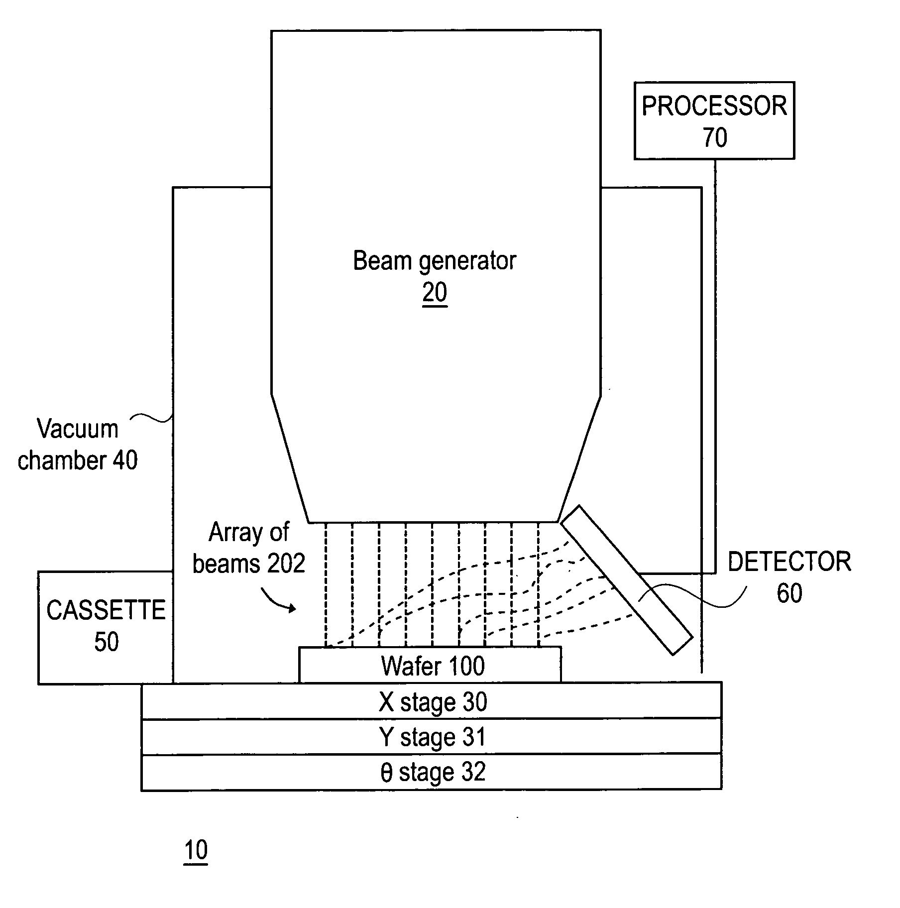
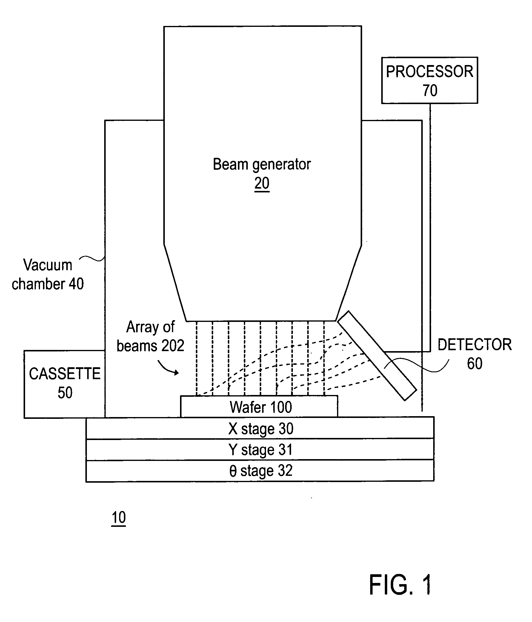
[0024] For convenience of explanation the following description relates to a system that inspects wafers by an array of electron beams. According to other embodiments of the invention the described system and method can be applied for metrology, for lithography and the like. The inspected object can be a reticle, a flat panel display, a MEMS device, and the like. The shape of the array can differ than a two dimensional grid, and the beams can include ion beams or light beams.

[0025]FIG. 1 illustrates an inspection system 10, according to an embodiment of the invention. System 10 includes a beam generator 20 that is capable of generating an array of charged partic...


PUM


Abstract

A multi beam inspection method and system. The inspection system includes: (i) a beam array generator adapted to generate an array of beams characterized by a beam array axis; and (ii) at least one mechanism adapted to position the object under the array of beams such that at least two beams that are positioned along a beam array axis scan substantially simultaneously at least two regions of interest of the object, wherein the first axis is oriented in relation to the beam array axis.

Description

CROSS-REFERENCE TO RELATED APPLICATIONS [0001] This application claims priority to U.S. Provisional Application titled “scanning regions of interest using a multi-beam system” filed Jun. 21, 2004, Ser. No. 60 / 581,817 which is incorporated herein by reference in its entirety.FIELD OF THE INVENTION [0002] The present invention relates to scanning an object that includes multiple regions of interest using an array of scanning beams, and especially of objects such as wafers or reticle using a charged particle beam array. BACKGROUND OF THE INVENTION [0003] Inspection of objects such as wafers or reticles using a scanning electron beam inspection tool is known in the art. Single beam inspection tools scan a wafer or reticle by a single beam. The relative size difference between wafers size and the beam cross section the throughput of such systems is limited. [0004] In order to increase the throughput of inspection and metrology systems various techniques were suggested. A first technique ...

Claims


Application Information

Patent Timeline
IPC IPC(8): G01N23/225H01J37/28
CPCG01N23/225H01J2237/2817H01J37/28
Inventor LITMAN, ALONSENDER, BENZION
Owner APPL MATERIALS ISRAEL LTD
Why Eureka
Try Eureka