Eureka AIR delivers breakthrough ideas for toughest innovation challenges, trusted by R&D personnel around the world.

Laser power controller and method for performing auto power control

a technology of power controller and power controller, which is applied in the direction of instruments, optical beam sources, semiconductor lasers, etc., can solve the problems of buffer under-run and disc servo system malfunction, and achieve the effects of preventing fatal errors, ensuring safety, and ensuring safety

Inactive Publication Date: 2005-12-22
MEDIATEK INC
View PDF1 Cites 15 Cited by
  • Summary
  • Abstract
  • Description
  • Claims
  • Application Information

AI Technical Summary

Benefits of technology

[0014] The laser power control circuit and the driving method thereof according to the present invention provide a sample / hold circuit that allows the laser power control circuit to be applied in high-speed read-and-write optical recording devices. Additionally, the laser power control circuit and the driving method disclose a digital control circuit that sets the most suitable output power by setting an optimal gain, and thereby modifies the output power to a target power so that the performance of the optical record device is greatly improved. Moreover, sometimes the situations of buffer under-run and malfunction of the disc servo system occur. Because these situations would result in burning interruption, the present invention is capable of outputting a steady state power control signal in a very short time before the linking writing begins, so as to promptly stabilize the power. Therefore the data will not be unreadable, and fatal errors are prevented.

Problems solved by technology

Moreover, sometimes the situations of buffer under-run and malfunction of the disc servo system occur.

Method used


Image

  • Laser power controller and method for performing auto power control
  • Laser power controller and method for performing auto power control
  • Laser power controller and method for performing auto power control

Examples


Embodiment Construction

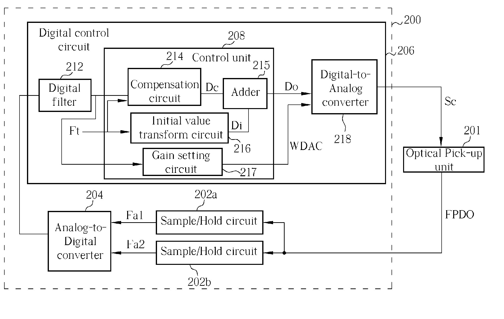
[0024] Please refer to FIG. 3. FIG. 3 is a diagram of an embodiment of the automatic power control circuit 200 according to the present invention. If data is to be written onto an optical recording medium (such as an optical disc), the laser power control circuit 200 is used for laser power control to the optical pick-up unit (OPU) 201, which means that the laser power control circuit 200 performs automatic power control (APC). As mentioned above, the OPU 201 sends a front photodiode output signal (FPDO) back to the laser power control circuit 200 so as to perform feedback control. In this embodiment, the laser power control circuit 200 comprises two sample / hold circuits 202a and 202b, an analog-to-digital converter (ADC) 204, and a digital control circuit 206. The digital control circuit 206 includes a control unit 208, a digital filter 212, and a digital-to-analog converter (DAC) 218. The control unit 208 comprises a compensation circuit 214, an adder 215, an initial value transfo...


PUM

PropertyMeasurementUnit
poweraaaaaaaaaa
laser poweraaaaaaaaaa
power control valueaaaaaaaaaa

Abstract

A laser power controller for performing an auto power control to control the laser power of an optical pick-up unit (OPU) includes: a sample / hold circuit used for sampling and holding a front photodiode output signal to generate an analog feedback signal; an analog-to-digital converter (ADC) electrically coupled to the sample / hold circuit for transferring the analog feedback signal into a digital feedback signal; and a digital control circuit electrically coupled to the ADC for generating a power control signal and outputting the power control signal to the OPU in order to control the laser power of the OPU. The front photodiode output signal corresponds to the laser power of the OPU.

Description

BACKGROUND OF INVENTION [0001] 1. Field of the Invention [0002] The invention relates to a laser power control circuit and a driving method thereof, and more particularly, to a laser power control circuit and a driving method thereof for implementing a high-speed sample / hold circuit and a digital control mechanism to perform automatic power control. [0003] 2. Description of the Prior Art [0004] With the rapid development of technology, the need for electronic information is constantly increasing. Most importantly, electronic information should be quickly stored in a very short time so as to preserve the information for later transmission. Therefore, the storage of electronic information becomes important, and the most popular way to store electronic information is to use an optical recording device. [0005] Generally speaking, an optical recording device often makes use of a laser diode (LD) as the source of light, but the output power of LDs depends on the working temperature, which...

Claims


Application Information

Patent Timeline
Patent Type & Authority Applications(United States)
IPC IPC(8): G11B7/125H01S3/00H01S5/042H01S5/0683
CPCH01S5/0683H01S5/042G11B7/1263
Inventor LI, YUNG-CHIHLIAO, HSUEH-KUNHSU, CHING-CHUAN
Owner MEDIATEK INC
Why Eureka
Eureka Blog
Learn More