Device and method for reducing peaks of a composite signal

Inactive Publication Date: 2005-12-22
LUCENT TECH INC
View PDF2 Cites 27 Cited by
  • Summary
  • Abstract
  • Description
  • Claims
  • Application Information

AI Technical Summary

Benefits of technology

[0014] In another exemplary embodiment of the present invention, a device is provided that reduces peaks of an input composite signal that has multiple carrier signals with respective frequency ba

Problems solved by technology

In reality, however, power amplifiers do not exhibit perfect linearity; i.e., they introduce distortion (e.g., non-linear amplitude distortion and non-linear phase distortion).
If the input signal has an amplitude that causes the power amplifier to operate outside the linear regions, the power amplifier may introduce nonlinear components or distortion into the signal.
Another shortcoming is that conventional clipping techniques may introduce undesirable spe

Method used


Image

  • Device and method for reducing peaks of a composite signal
  • Device and method for reducing peaks of a composite signal
  • Device and method for reducing peaks of a composite signal

Examples


Embodiment Construction

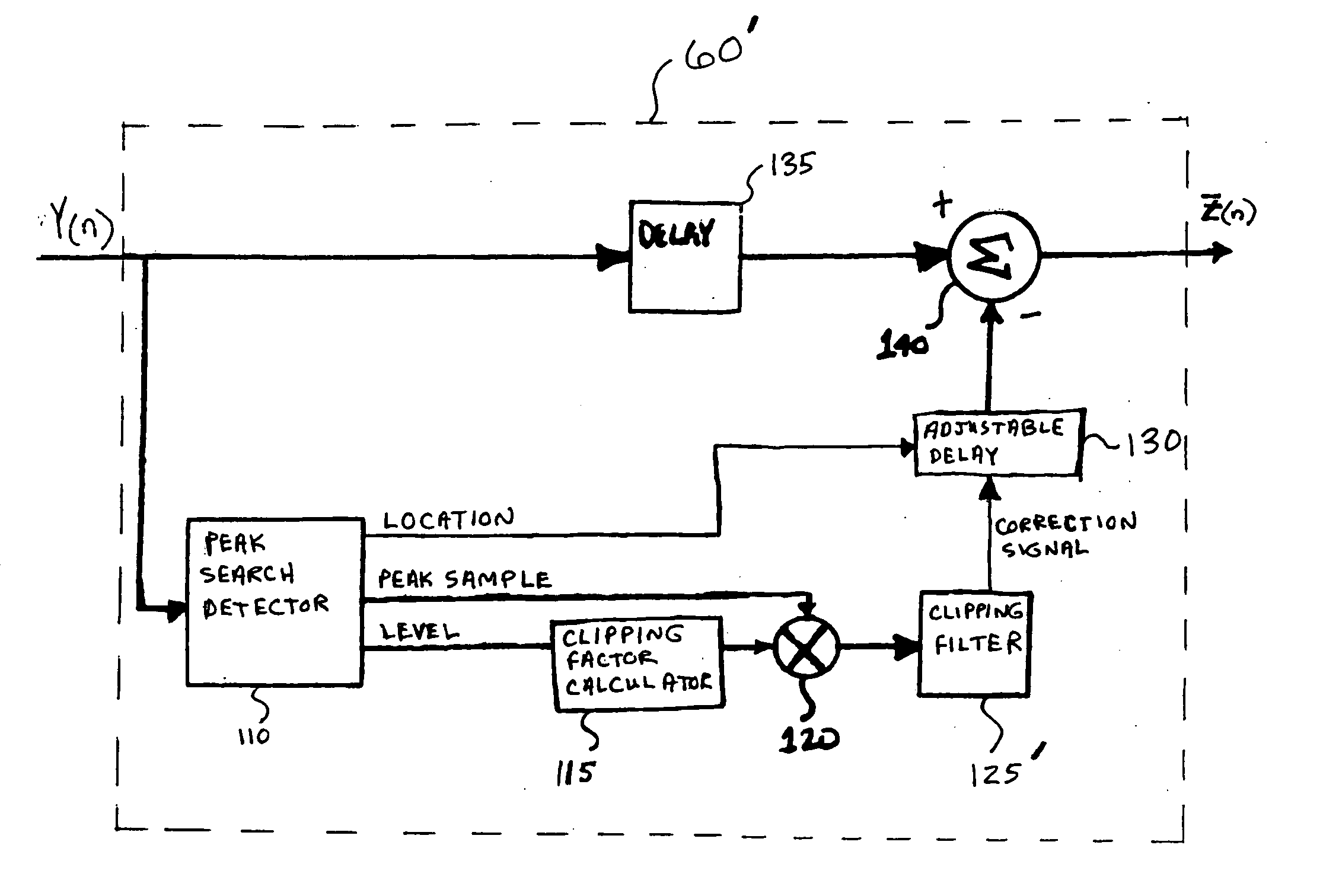
[0010] Exemplary embodiments of the present invention take advantage of the bandwidth gaps that are usually located between respective frequency bandwidths of carrier signals of a composite signal.

[0011] In an exemplary embodiment of the present invention, a method is provided for limiting at least one peak of a composite signal having at least two carrier signals at respective frequency bandwidths. The method may involve generating a correction signal based on at least one detected peak of the composite signal so that the correction signal has a spectral shape that places energy in at least one bandwidth gap located between the respective frequency bandwidths of the carrier signals. The correction signal and the composite signal may be combined so that the correction signal is located at the detected peak in time domain. The peak of the carrier signal may be detected from a window of samples of the composite signal. The detected peak may be multiplied by a clipping factor to calcu...


PUM


Abstract

A method of limiting at least one peak of a composite signal having multiple carriers signals involves placing energy in at least one bandwidth gap located between respective frequency bandwidths of carrier signals.

Description

BACKGROUND OF THE INVENTION [0001] 1. Field of the Invention [0002] The present invention generally relates to a device and method for limiting peaks of a signal and, more particularly, to a device and method for reducing the peak-to-average ratio (“PAR”) of a composite signal including at least two carrier signals at respective frequency bandwidths. [0003] 2. Description of Related Art [0004] RF power amplifiers are widely used to transmit signals in communication systems. Ideally, the power amplifier would provide a uniform gain throughout a dynamic range so that the output signal of the amplifier is a correct, amplified version of an input signal. In reality, however, power amplifiers do not exhibit perfect linearity; i.e., they introduce distortion (e.g., non-linear amplitude distortion and non-linear phase distortion). Whether the power amplifier is operating in a linear or nonlinear region may depend on the amplitude of the input signal. If the input signal has an amplitude th...

Claims


Application Information

Patent Timeline
IPC IPC(8): H04L25/03H04L27/26H04L27/28
CPCH04L27/2623
Inventor OBERNOSTERER, FRANK GERHARD ERNSTSANWAL, KUMUD KUMAR
Owner LUCENT TECH INC
Why Eureka
Try Eureka