Motor drive device and image-forming device including the same

a technology of motor drive and image forming device, which is applied in the direction of motor/generator/converter stopper, electronic commutator, dynamo-electric converter control, etc., can solve the problems of increasing complicated configuration, etc., and achieve the effect of reducing the size and cost of the devi

Active Publication Date: 2005-12-22
BROTHER KOGYO KK
View PDF4 Cites 18 Cited by
  • Summary
  • Abstract
  • Description
  • Claims
  • Application Information

AI Technical Summary

Benefits of technology

[0006] In order to solve the above problems, an object of the present invention is to provide a motor drive device to ...

Problems solved by technology

Therefore, the circuit configuration tends to be complicated, which may lead to an increase in size and cost of the device.
When the motor drive circuit is mounted ...

Method used


Image

  • Motor drive device and image-forming device including the same
  • Motor drive device and image-forming device including the same
  • Motor drive device and image-forming device including the same

Examples


Embodiment Construction

[0026] Preferred embodiments of the present invention will be described with reference to the accompanying drawings. The following description will be made for explaining an overall configuration of a laser printer 1.

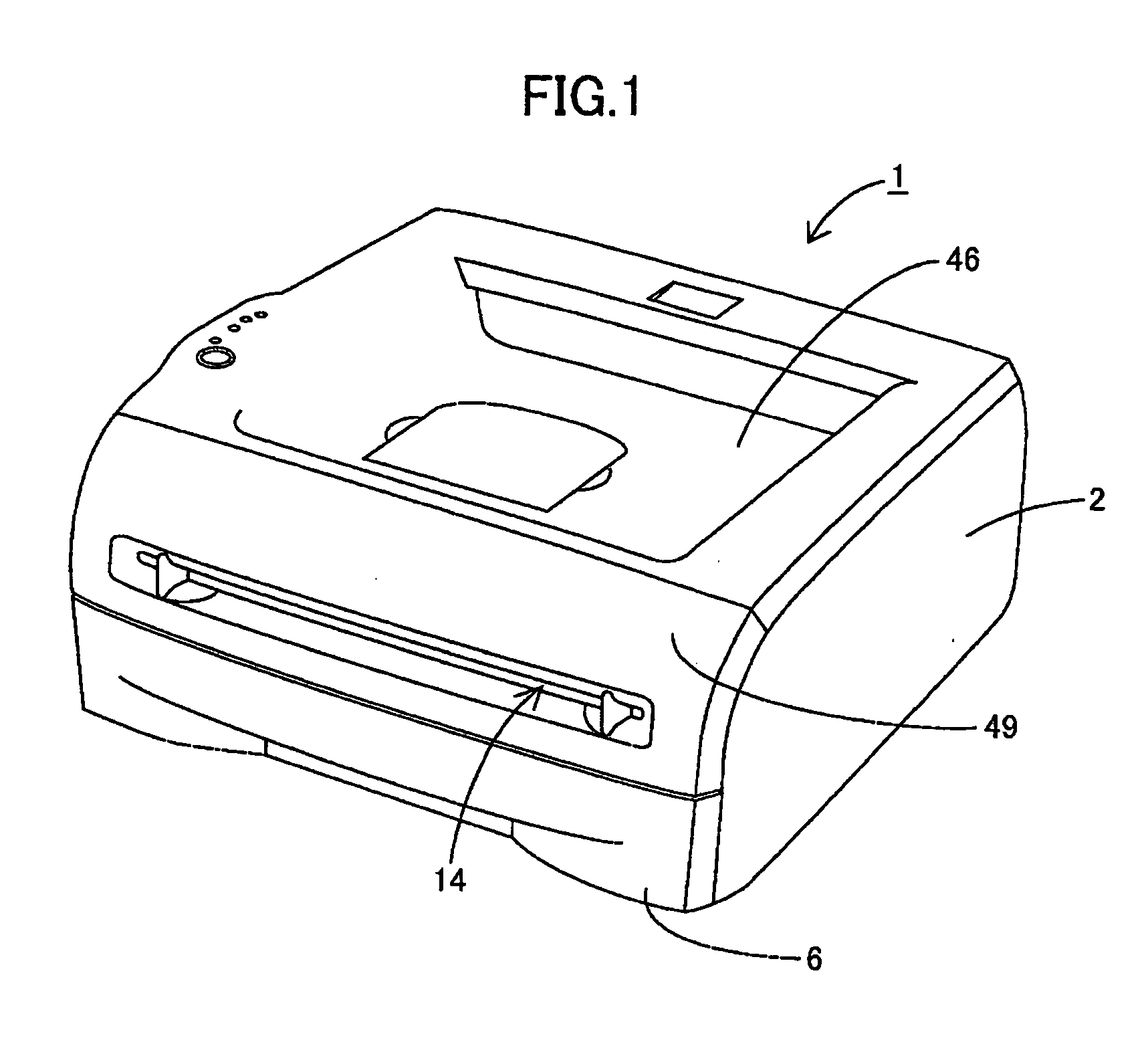
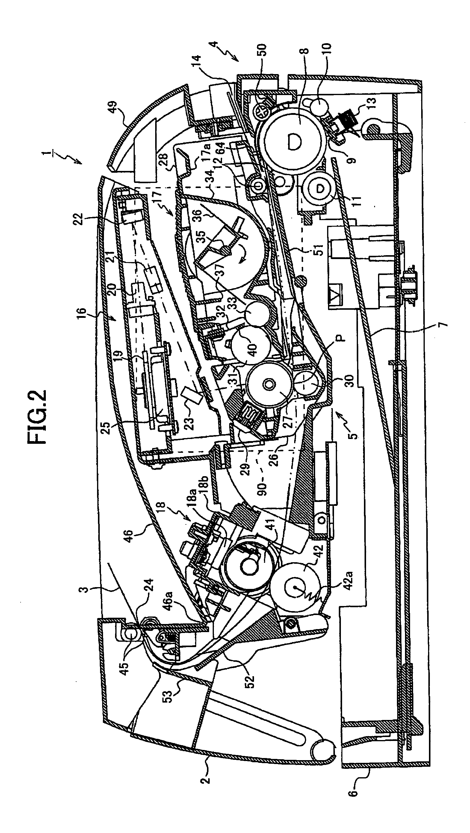
[0027] Referring to FIG. 1, the printer 1 has a main casing 2. Referring to FIG. 2, the printer 1 includes a feeder portion 4 for supplying paper 3 and an image formation portion 5 for forming an image on the paper 3 within the main casing 2. The printer 1 further has a paper-delivery tray 46 in an upper portion of the printer 1 for carrying the printed paper 3. It should be noted that the expressions “front”, “rear”, “above” and “below” are used throughout the description to define the various parts when the printer 1 is disposed in an orientation in which it is intended to be used.

[0028] As shown in FIG. 2, the feeder portion 4 is provided with a paper-supply tray 6, a paper pressure plate 7 provided within the paper-supply tray 6, a feed roller 11 provided above on...


PUM


Abstract

A motor drive device having a motor drive unit, a controller, and a rotational detector. The motor drive unit drives a brushless DC motor, the brushless DC motor has a rotor. The controller produces a motor driving signal to drive the brushless DC motor. The a rotational detector detects a rotational state of the brushless DC motor to produce a rotational state signal. The controller receives the rotational state signal from the rotational detector, determines a phase-switching timing to switch a phase of the brushless DC motor based on the rotational state signal, and transmits the phase-switching timing as the motor driving signal to the motor driver.

Description

BACKGROUND OF THE INVENTION [0001] 1. Technical Field [0002] The invention relates to a motor drive device and an image-forming device including the same. [0003] 2. Related Art [0004] A conventional motor drive device for controlling a brushless DC motor is provided with a control circuit that performs digital control and a motor drive circuit that drives the motor in response to instructions from the control circuit. For example, Japanese Patent Publication No. 2001-61297 discloses an image-forming device having a speed determination circuit and a motor lock circuit provided within an application-specific integrated circuit (ASIC) chip. The ASIC produces a signal for a motor driver IC having a Hall-effect amplifier and a phase-switching circuit, thereby driving the brushless DC motor. [0005] However, in the conventional motor drive device, a phase-switching circuit is provided within the motor drive circuit, as disclosed in Japanese Patent Publication No. 2001-61297. Therefore, the...

Claims


Application Information

Patent Timeline
IPC IPC(8): B41J2/44B41J2/47H02P5/46H02P6/06H02P6/08H02P6/17H02P6/28H02P7/06
CPCH02P6/14H02P6/002H02P6/28
Inventor SUGIMOTO, TASUKUOKAMOTO, HISANORI
Owner BROTHER KOGYO KK
Why Eureka
Try Eureka