
Hemostasis valve and method for assembling same

a technology of hemostasis valve and valve body, which is applied in the direction of diaphragm valve, engine diaphragm, mechanical apparatus, etc., can solve problems such as backflow bleeding, and achieve the effect of less spring for

Inactive Publication Date: 2005-12-22
APPL MEDICAL RESOURCES CORP
View PDF0 Cites 27 Cited by
  • Summary
  • Abstract
  • Description
  • Claims
  • Application Information

AI Technical Summary

Benefits of technology

[0007] In another aspect of the invention, the protrusions in the cam body are two or more in number and are disposed around the channel in the sealing member at substantially equally spaced angular intervals. For example, the protrusions may be four in number and angularly spaced at 90 degree intervals around the sealing member. The spring may be a torsion spring disposed over the cam body or a compression spring disposed between the first and second finger tabs. The sealing apparatus may further comprise a cap adapter operably attached at a distal end of the cam body, and an end cap operably attached at a proximal end of the cam body. In another aspect of the invention, the pins may be variably shaped so as to exert different pressure along the surface of the protrusions. In particular, at least one of a radius, width, length, and angle of engagement of the pins may be varied to exert different pressure against the surface of the protrusions. An advantage of this aspect of the invention is less spring force is required to completely seal the sealing member at the end of a closing stroke.

Problems solved by technology

These seals may also be introduced into regions under pressure that may cause backflow bleeding if they are not properly controlled.

Method used


Image

  • Hemostasis valve and method for assembling same
  • Hemostasis valve and method for assembling same
  • Hemostasis valve and method for assembling same

Examples


Embodiment Construction

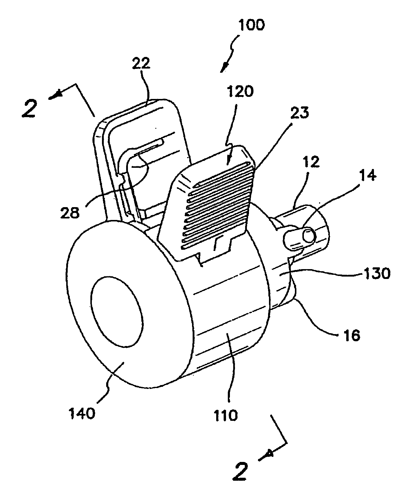
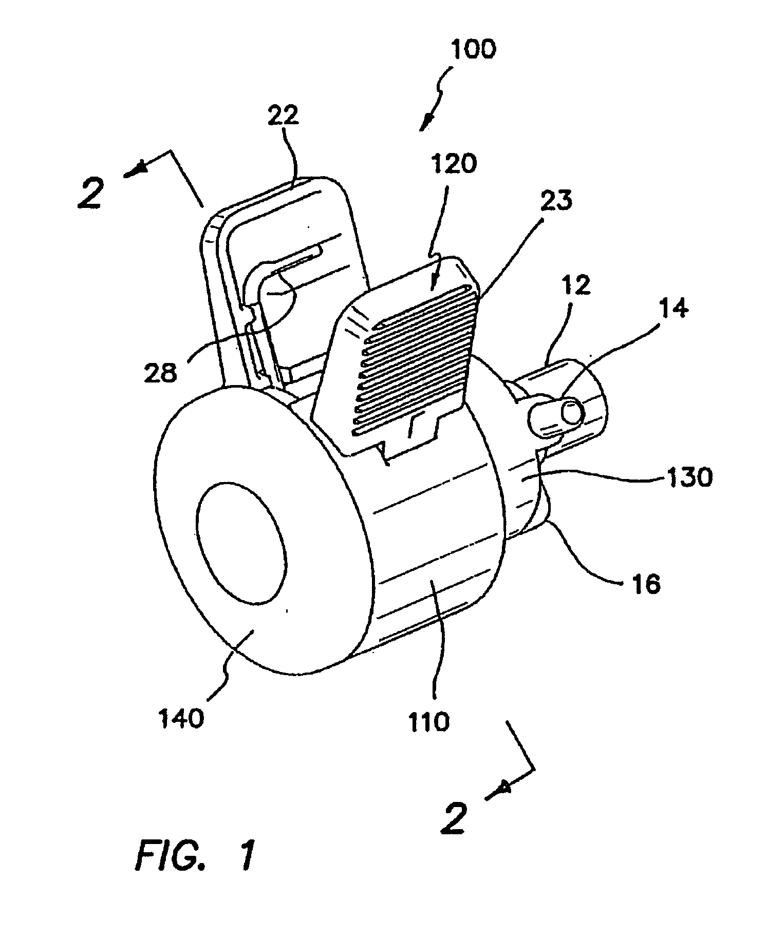
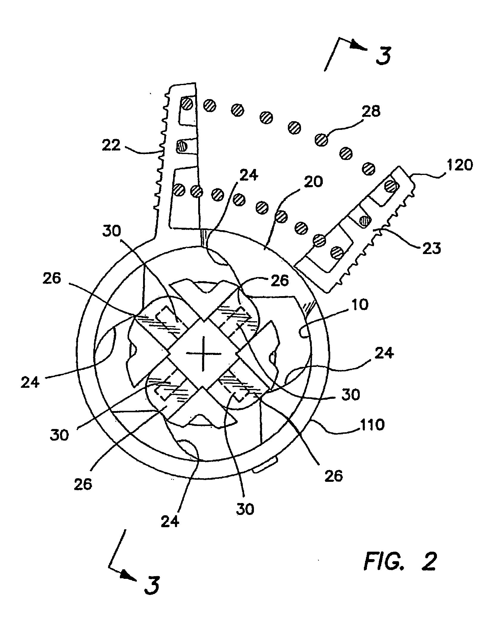
[0014] Referring to FIG. 1, there is shown a sealing apparatus 100 in accordance with a first embodiment of the invention comprising a housing body 110 including a stationary finger tab 22, a 2-piece cam body 120, a cap adapter 130 and an end cap 140. The housing body 110 includes an enlarged open-ended cavity 10 (see FIG. 2) and the cap adapter 130 includes a tubular conduit fitting 12 communicating with the cavity 10. In one embodiment, the cap adapter 130 further includes a side port 14 for communicating with the interior of the fitting 12. The cap adapter 130 may include a suture loop 16 that is formed integrally with the cap adapter 130. Referring to FIG. 2, the housing body 110 further includes an elongate arcuate slot 20 extending through the housing body 110 to accommodate a finger tab 23 of the cam body 120 in apposition to the stationary finger tab 22. The slot 20 opens through one end of the housing body 110 to facilitate assembly of the apparatus 100 as further discussed...


PUM


Abstract

The invention is directed to a sealing apparatus for sealing around a medical instrument, the sealing apparatus comprising a housing body; a two-piece cam body disposed inside the housing body; a sealing member disposed inside the cam body and having a channel extending axially of the cam body, the sealing member having at least two protrusions disposed around the channel; a plurality of pins operable to engage with the protrusions of the sealing member for movement relative to the cam body to radially compress the sealing member against and form a seal around the medical instrument; and biasing means for compressing the sealing member. In one aspect of the invention, the biasing means includes a first finger tab fixed to and extending laterally from the housing body, a second finger tab operatively associated with the cam body for movement relative to the housing body, the second finger tab extending laterally from the housing body in apposition to the first finger tab, and a spring being disposed between the first and second finger tabs to normally force the finger tabs apart. In another aspect, the protrusions in the cam body are more than two in number and are disposed around the channel at substantially equally spaced angular intervals. In another aspect, at least one of a radius, width, length, and angle of engagement of the pins may be varied or changed to exert different pressure against the surface of the protrusions. In another aspect, a process of assembling the sealing apparatus of the invention is disclosed, the process comprising the steps of placing the pins onto or against the protrusions of the sealing member; placing a first cam body half and a second cam body half over the sealing member and joining the two cam body halves together forming the 2-piece cam body; placing the housing body over the cam body; and placing the biasing means over the cam body inside the housing body.

Description

BACKGROUND OF THE INVENTION [0001] 1. Field of the Invention [0002] This invention generally relates to access devices and, more specifically, to seals and other closure mechanisms applicable to devices. [0003] 2. Discussion of the Relevant Art [0004] Access devices are commonly used in surgery to facilitate the introduction of various surgical instruments into vessels, conduits, cavities and other interior regions of the body. These access devices include, for example, seals which facilitate passing of an instrument such as a balloon catheter into a vessel, and trocars which facilitate the introduction of laparoscopic instruments into the abdomen of the body. Seals that operate to pass instruments into the vascular system must also operate as hemostasis valves that prevent blood loss during surgery. These seals may also be introduced into regions under pressure that may cause backflow bleeding if they are not properly controlled. [0005] It is thus desirable to provide for an access...

Claims


Application Information

Patent Timeline
Patent Type & Authority Applications(United States)
IPC IPC(8): A61M39/06F16J15/02F16K7/06
CPCA61M39/0613F16K7/065A61M2039/0673
Inventor GADBERRY, DONALD L.
Owner APPL MEDICAL RESOURCES CORP
Learn More