Medical device with an electrically conductive anti-antenna member
Inactive Publication Date: 2005-12-22
BIOPHAN TECH
View PDF99 Cites 60 Cited by
Summary
Abstract
Description
Claims
Application Information
AI Technical Summary
This helps you quickly interpret patents by identifying the three key elements:
Problems solved by technology
Method used
Benefits of technology
Problems solved by technology
The use of the magnetic-resonance imaging process with patients who have implanted medical assist devices; such as cardiac assist devices or implanted insulin pumps; often presents problems.
Since the sensing systems and conductive elements of these implantable devices are responsive to changes in local electromagnetic fields, the implanted devices are vulnerable to external sources of severe electromagnetic noise, and in particular, to electromagnetic fields emitted during the magnetic resonance imaging procedure.
A common implantable pacemaker can, under some circumstances, be susceptible to electrical interference such that the desired functionality of the pacemaker is impaired.
Such electrical interference can damage the circuitry of the cardiac assist systems or cause interference in the proper operation or functionality of the cardiac assist systems.
For example, damage may occur due to high voltages or excessive currents introduced into the cardiac assist system.
Therefore, it is required that such voltages and currents be limited at the input of such cardiac assist systems, e.g., at the interface.
However, such protection, provided by zener diodes and capacitors placed at the input of the medical device, increases the congestion of the medical device circuits, at least one zener diode and one capacitor per input/output connection or interface.
This is contrary to the d
Method used
Image
Click on the blue label to locate the original text in one second.
Reading with bidirectional positioning of images and text.
Examples
Embodiment Construction
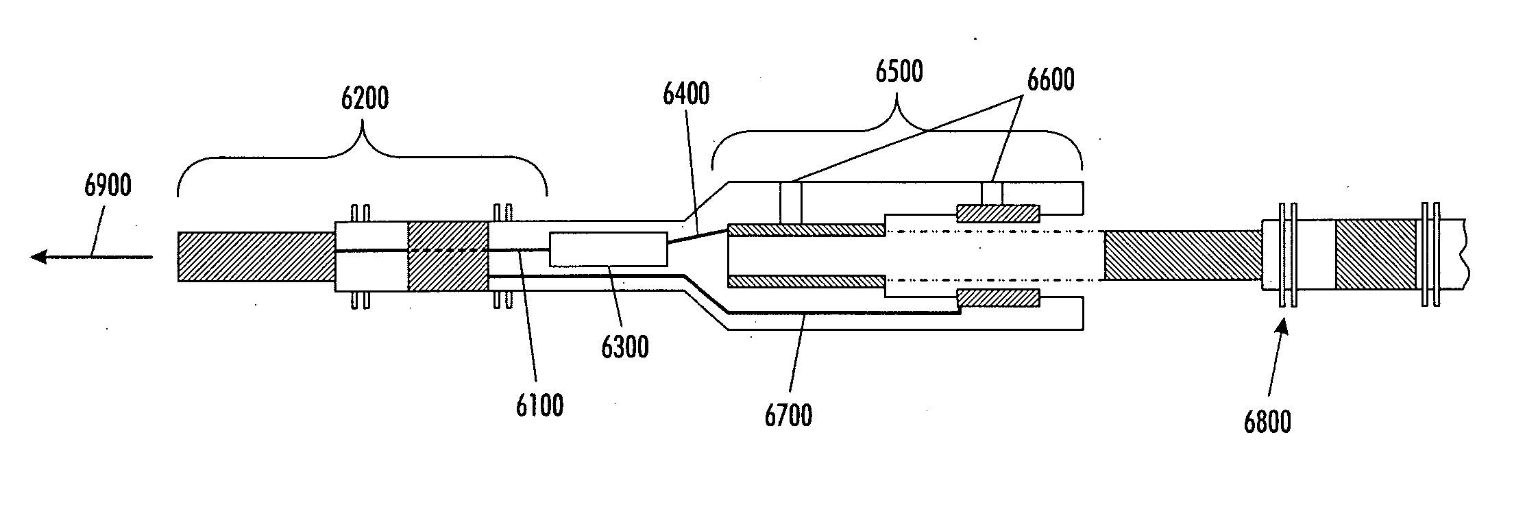
[0082] As noted above, a medical device includes an anti-antenna device to prevent or significantly reduce damaging heat, created by currents or voltages induced by outside electromagnetic energy (namely magnetic-resonance imaging), to a tissue area.
[0083] More specifically, the present invention is directed to a medical device that includes anti-antenna device, which significantly reduces the induced current on the “signal” wire of a pacing lead when the pacing lead is subjected to the excitation signal's frequency of a magnetic-resonance imaging scanner without significantly altering a low frequency pacing signal. The low frequency pacing signal may be generated by an implantable pulse generator or other pulse generator source outside the body.
[0084] To provide an anti-antenna device, the present invention utilizes a resonant circuit or circuits in line with a lead. The lead may be a signal wire of the pacing lead. Although the following descriptions of the various embodiments o...
PUM
Abstract
A lead includes a conductor having a distal end and a proximal end and a resonant circuit connected to the conductor. The resonant circuit has a resonance frequency approximately equal to an excitation signal's frequency of a magnetic resonance imaging scanner or a resonance frequency not tuned to an excitation signal's frequency of a magnetic resonance imaging scanner so as to reduce the current flow through a tissue area, thereby reducing tissue damage. The resonant circuit may be included in an adapter that provides an electrical bridge between a lead a medical device such as an electrode, sensor, or signal generator. The resonant circuit may also be included directly in the housing of a medical device.
Description
PRIORITY INFORMATION [0001] The present application is a continuation-in-part of co-pending U.S. patent application Ser. No. 10 / 922,359, filed on Aug. 20, 2004. The present application claims priority, under 35 U.S.C. §120, from co-pending U.S. patent application Ser. No. 10 / 922,359, filed on Aug. 20, 2004, said U.S. patent application Ser. No. 10 / 922,359, filed on Aug. 20, 2004 claiming priority, under 35 U.S.C. §119(e), from U.S. Provisional Patent Application Ser. No. 60 / 497,591, filed on Aug. 25, 2003. The present application claims priority, under 35 U.S.C. §119(e), from U.S. Provisional Patent Application Ser. No. 60 / 497,591, filed on Aug. 25, 2003. Also, the present application claims priority, under 35 U.S.C. §119(e), from U.S. Provisional Patent Application Ser. No. 60 / 698,393, filed on Jul. 12, 2005. The entire content of U.S. patent application Ser. No. 10 / 922,359 is hereby incorporated by reference. The entire contents of US Provisional Patent Applications, Ser. No. 60 / 4...
Claims
Application Information
Patent Timeline
Application Date:The date an application was filed.
Publication Date:The date a patent or application was officially published.
First Publication Date:The earliest publication date of a patent with the same application number.
Issue Date:Publication date of the patent grant document.
PCT Entry Date:The Entry date of PCT National Phase.
Estimated Expiry Date:The statutory expiry date of a patent right according to the Patent Law, and it is the longest term of protection that the patent right can achieve without the termination of the patent right due to other reasons(Term extension factor has been taken into account ).
Invalid Date:Actual expiry date is based on effective date or publication date of legal transaction data of invalid patent.