

Power source device for a vehicle
a power source device and vehicle technology, applied in the direction of electric propulsion mounting, dc-ac conversion without reversal, transportation and packaging, etc., can solve the problem of considerable weight and volume of the core, and achieve the effect of reducing the siz
- Summary
- Abstract
- Description
- Claims
- Application Information
AI Technical Summary
Benefits of technology
Problems solved by technology
Method used
Image

Examples
first embodiment
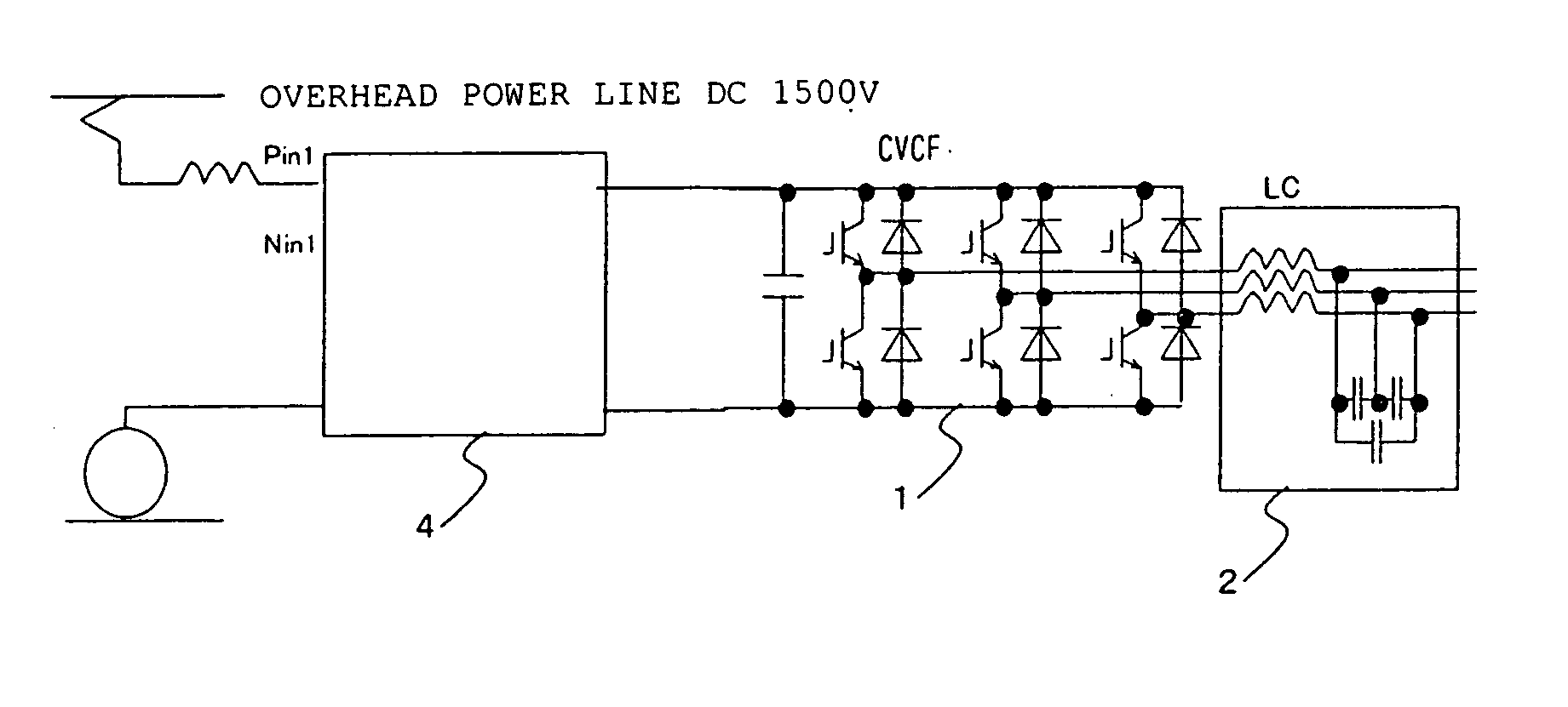
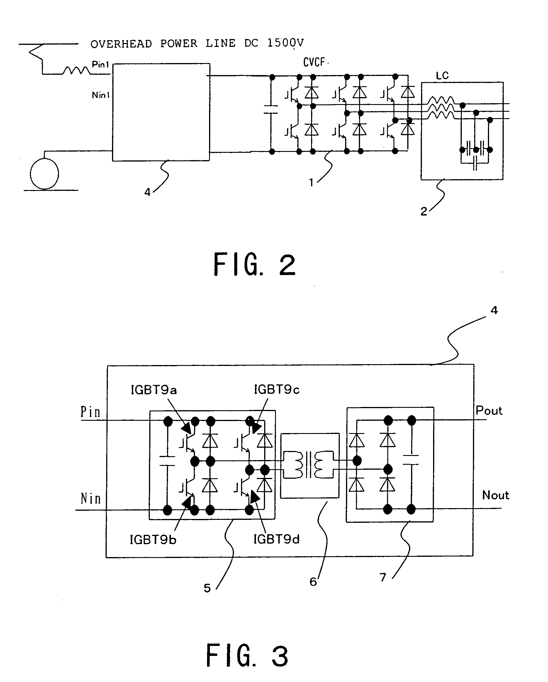
[0034] A vehicle power source device according to a first embodiment of the present invention is described in detail with reference to the drawings. FIG. 2 is a layout diagram of a vehicle power source device according to a first embodiment of the present invention. FIG. 3 is a layout diagram of a DC / DC converter of a vehicle power source device according to the first embodiment of the present invention.
[0035] It is known that an insulating transformer 3 can typically be made lighter in weight and smaller in size as the frequency is increased. Accordingly, in the vehicle power source device according to the first embodiment of the present invention, as shown in FIG. 2 and FIG. 3, the overhead line power is temporarily converted by an inverter 5 within the DC / DC converter 4 into a high frequency such as 50 kHz and is then rectified by a rectifier 7 after insulation has been achieved by a high frequency transformer 6. The DC voltage rectified by the rectifier 7 is converted to three-...
second embodiment
[0037] A second embodiment of a vehicle power source device according to the present invention is described in detail with reference to the drawings. FIG. 4 is a layout diagram of a vehicle power source device according to the second embodiment of the present invention. FIG. 5 is a layout diagram of a DC / DC converter of the vehicle power source device of the second embodiment of the present invention. FIG. 6 is a diagram of the switching action of the inverter. In the description, where it is necessary to distinguish identical parts, these are distinguished by adding a suffix after the numeral.
[0038] When a vehicle power source device according to the first embodiment of the present invention was actually manufactured employing a high frequency insulating transformer 3, it was found that it is necessary to lead out the high frequency, high-voltage high-power main circuit wiring into the housing of the DC / DC converter 4 and it was found that problems could arise due to generation of...
third embodiment
[0053] A vehicle power source device according to a third embodiment of the present invention is described in detail with reference to the drawings. FIG. 7 is a layout diagram of a vehicle power source device according to the third embodiment of the present invention. FIG. 8 is a layout diagram of a vehicle power source device according to another modified example of the present invention. FIG. 9 is a layout diagram of the case in which a DC / DC converter according to the third embodiment of the present invention is arranged on a printed circuit board. Parts which are structurally identical with those shown in FIG. 2 to FIG. 6 are given the same reference symbols and further description thereof is omitted.
[0054] In a vehicle power source device according to the third embodiment of the present invention, the DC output side of the first unit DC / DC converter 8a and the DC output side of the second DC / DC converter 8b are series-connected to constitute a first series circuit and the DC o...
PUM
 Abstract
Description
Claims
Application Information