Integrated heat exchanger and muffler unit

Inactive Publication Date: 2005-12-29
MODINE MFG CO
View PDF17 Cites 30 Cited by
  • Summary
  • Abstract
  • Description
  • Claims
  • Application Information

AI Technical Summary

Benefits of technology

[0004] An object of this invention is to design an air compressor aftercooler that not only meets the heat transfer performance requirements but also satisfi

Problems solved by technology

What comes with this compression process are the annoying noises due to the compressor'

Method used


Image

  • Integrated heat exchanger and muffler unit
  • Integrated heat exchanger and muffler unit
  • Integrated heat exchanger and muffler unit

Examples


Example

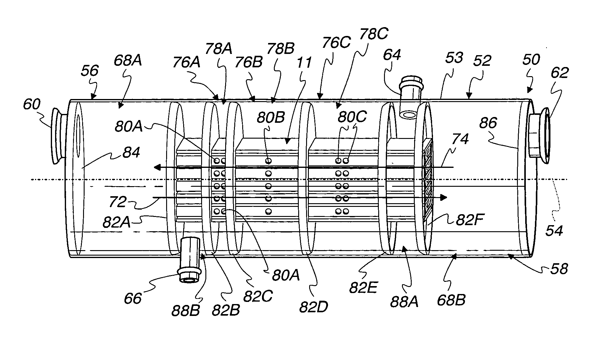
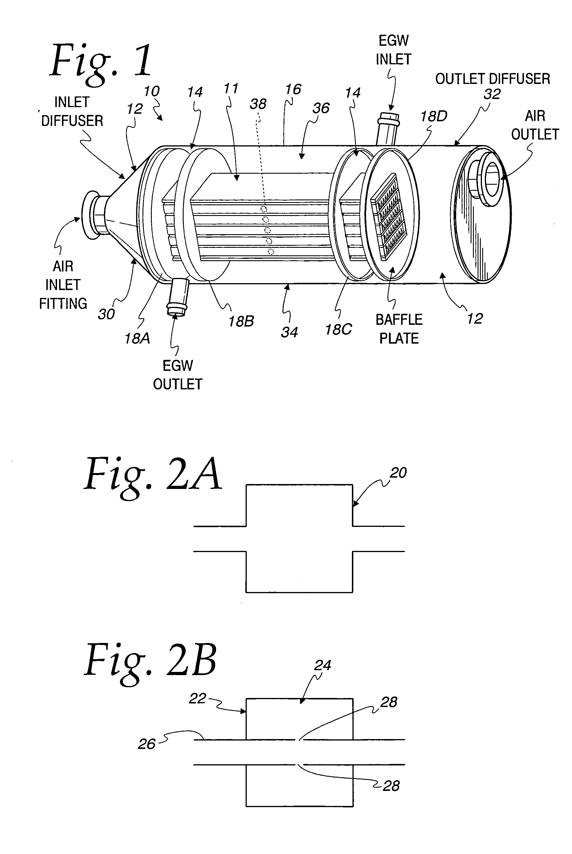
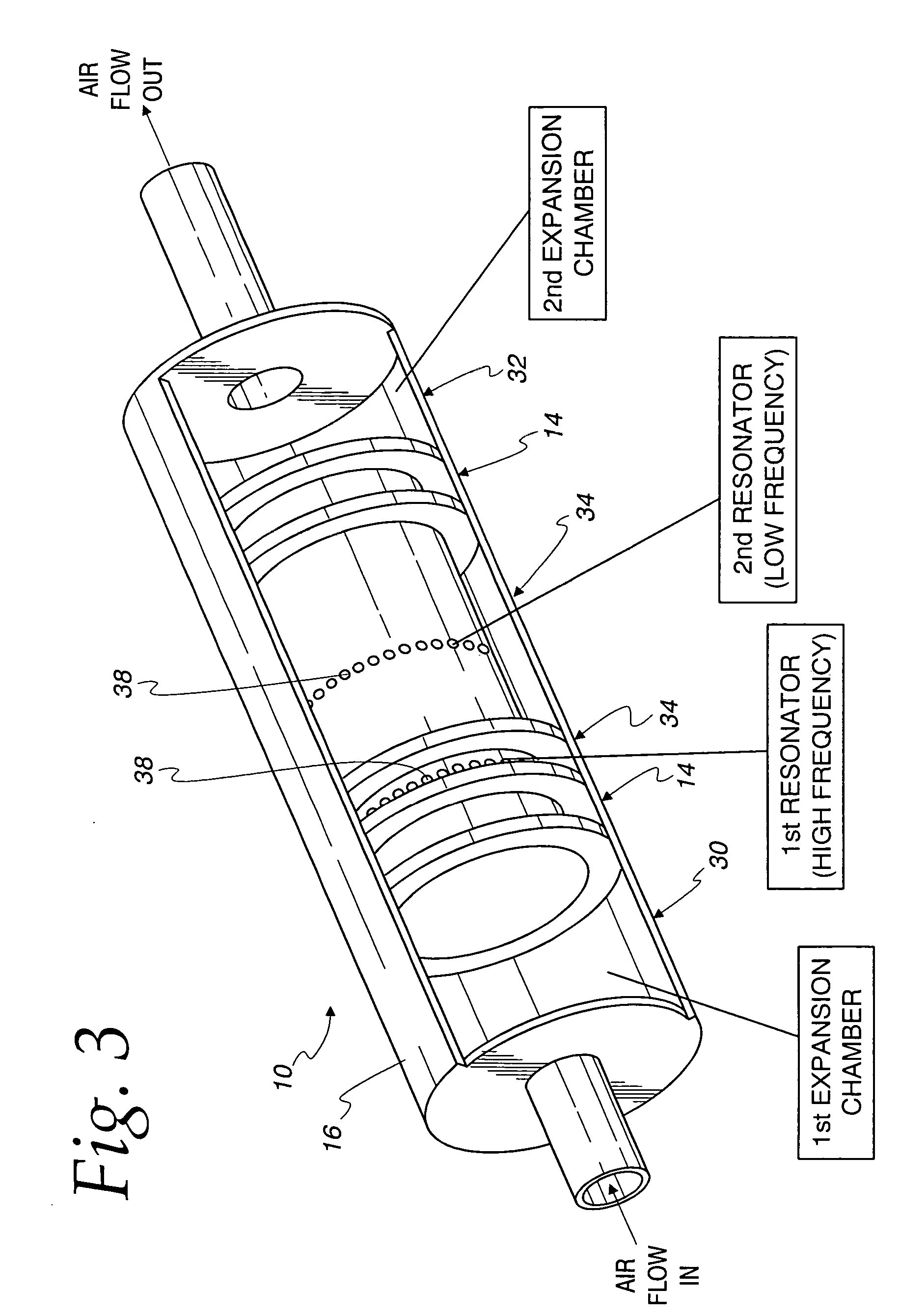
[0047] In an earlier conceptual design of an air aftercooler 10, a heat exchanger core 11 of bar-plate construction and all its air and coolant manifolds 12 and 14, respectively, could be brazed at one time using a cylindrical tube housing 16 and some internal baffle plates 18A-18D. FIG. 1 shows one possible configuration as an example of this design. The intention of the design was to avoid welding inlet / outlet distribution tanks on both the air side and coolant side of the heat exchanger core 11 for simplified manufacturing purpose.

[0048] In addition to its aforementioned welding free merit, the configuration of this design also gives the chance to incorporate some noise reduction function in it without affecting its design performance as a heat exchanger. According to the plain wave acoustical theory, there are two basic types of noise reduction mechanism: expansion chamber and resonator, as illustrated in FIGS. 2A and 2B, respectively. The mechanism of the expansion chamber typ...


PUM


Abstract

An integrated heat exchanger and muffler unit (50,120,140) is provided for transferring heat between a first fluid and a second fluid, and for muffling the noise of the first fluid. The unit includes a housing (52) including a first inlet (60) for the first fluid, a first outlet (62) for the first fluid, a second inlet (64) for the second fluid, and a second outlet (66) for the second fluid. The unit (50,120,140) further includes a resonator (76) in the housing (52) and connected between the first inlet and outlet (60,62) to muffle noise in the first fluid, and a heat exchanger core (11,122) in the housing (52) connected to the first and second inlets and outlets to transfer heat between the first and second fluids. In one embodiment, the heat exchanger core surrounds the resonator. In another embodiment, the resonator surrounds the heat exchanger core.

Description

CROSS-REFERENCE TO RELATED APPLICATION [0001] This application claims priority to provisional application Ser. No. 60 / 569,939, filed May 11, 2004, entitled “Noise Reduction Heat Exchanger”.FIELD OF THE INVENTION [0002] This invention relates to integrated heat exchangers and mufflers, and in more particular applications to integrated heat exchangers and mufflers for use in a pressurized fuel cell system at a location downstream from the air compressor for the cathode air flow. BACKGROUND OF THE INVENTION [0003] In a pressurized fuel cell system where air is needed as oxidant, an air compressor is generally in place to supply the air at higher pressure above the atmosphere. What comes with this compression process are the annoying noises due to the compressor's internal cyclic moving or rotating parts, as well as the high temperature air output. Therefore, in a typical system design of this kind, a noise reduction silencer / muffler usually follows the gas compressor to muffle the nois...

Claims


Application Information

Patent Timeline
IPC IPC(8): F01N1/00F01N1/02F01N1/08F01N5/02F01N7/00F28D9/00H01M8/02
CPCF01N1/003F01N1/02F01N1/085F01N2230/00F28F2265/28F28D9/0062H01M8/04074Y02E60/50F01N2240/02F01N5/02F01N1/00F01N5/00F01N13/00
Inventor VOSS, MARK G.CAO, LIPINGMROSS, GREGORY A.
Owner MODINE MFG CO
Why Eureka
Try Eureka