Electrode for projection welding

a technology of projection welding and electrodes, applied in the direction of cooled electrodes, soldering apparatus, auxillary welding devices, etc., can solve the problems of uneconomical replacement parts cost and productivity drop, and achieve the effect of reducing the recessing phenomenon of the end cover surface and preventing thermal degradation

Inactive Publication Date: 2005-12-29
KUBUSHIKI KAISHA AOYAMA
View PDF5 Cites 15 Cited by
  • Summary
  • Abstract
  • Description
  • Claims
  • Application Information

AI Technical Summary

Benefits of technology

[0006] According to an embodiment of the invention, an electrode for projection welding has an end cover made of metal and having a through hole and attached to the end of a cylindrical main body made of metal, and a guide sleeve made of insulation material is disposed in said main body, the guide sleeve having a part receiving hole formed in the end thereof in a state communicating with the through hole in said end cover, and a cooling passage for fluid is formed for cooling the guide sleeve. As a result, a cooling passage for cooling the gu...

Problems solved by technology

Therefore, the durability of the end cover 10 decreases, resulting in a short cycle of replacement of the end cover 10, greatly increasing the frequenc...

Method used


Image

  • Electrode for projection welding
  • Electrode for projection welding
  • Electrode for projection welding

Examples


Embodiment Construction

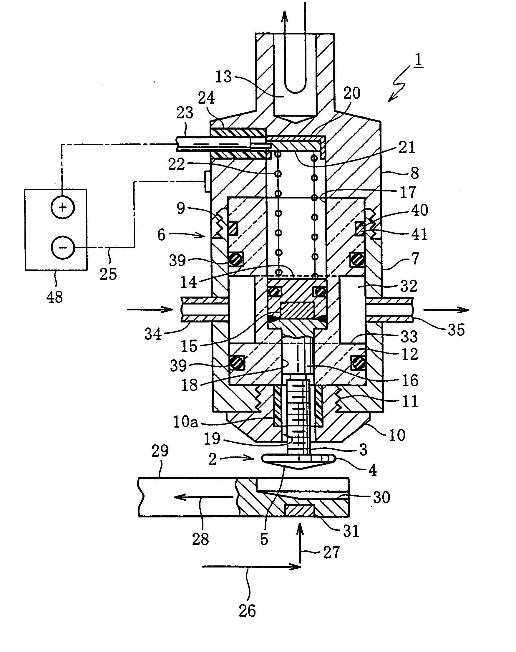
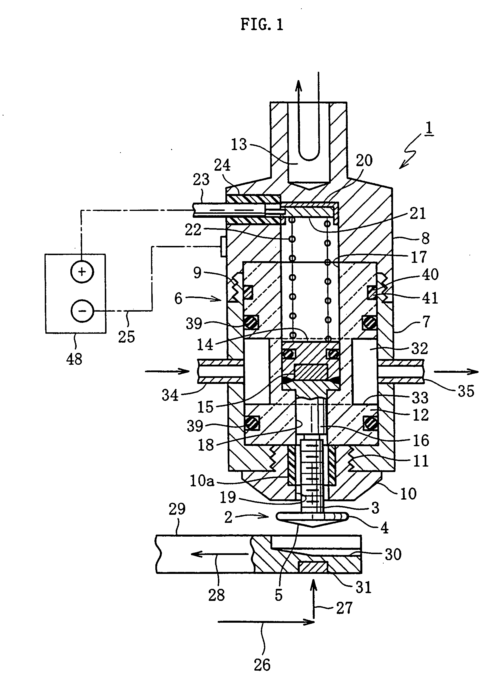
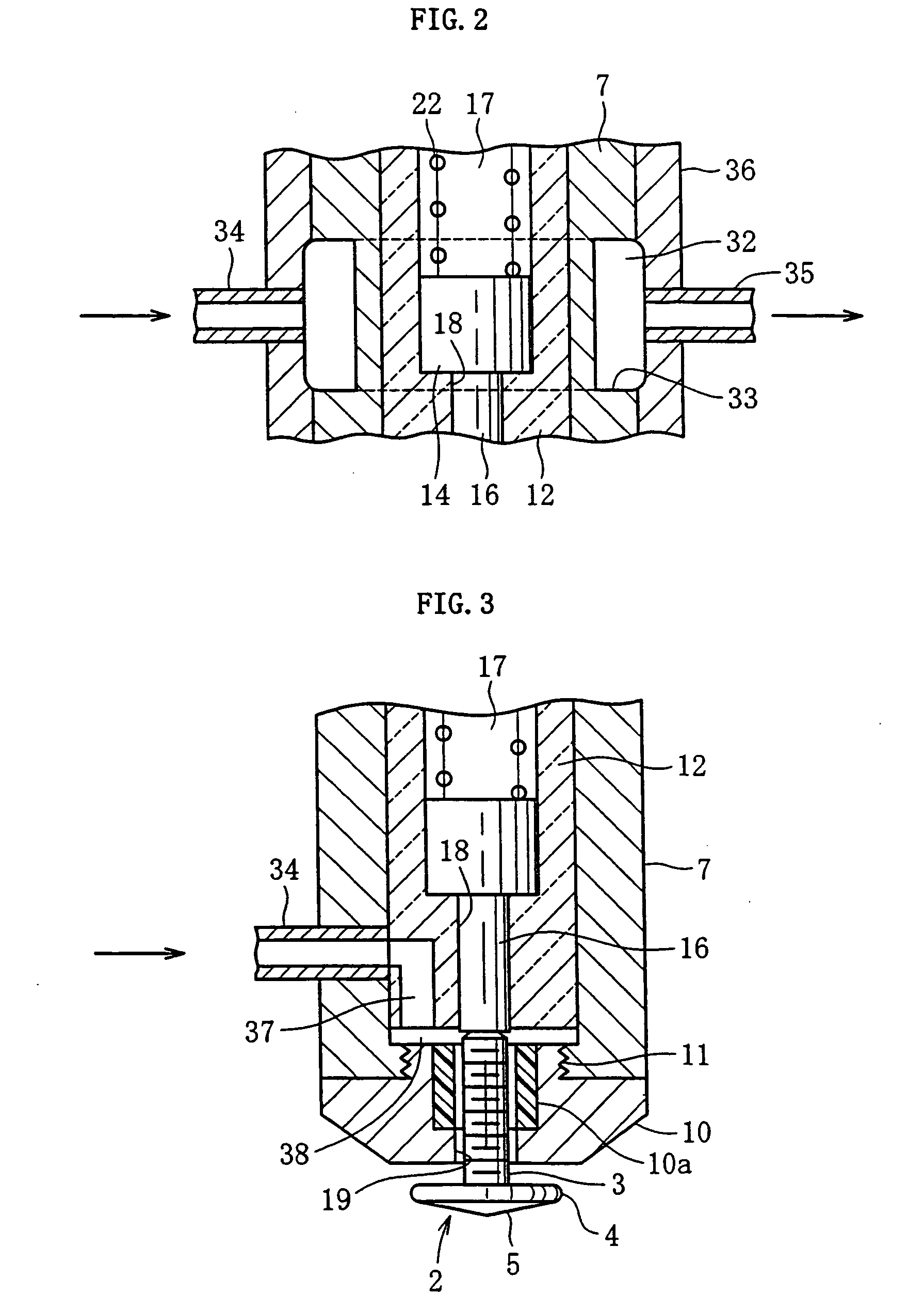
[0016] First, an embodiment shown in FIG. 1 will be described. A part 2 in this case is a projection bolt composed of a stem 3, flange 4 and a welding projection 5. The main body 6 of an electrode 1 is composed of a welding-side member 7 of copper-chromium alloy and a fixed-side member 8 also of copper-chromium alloy, which are decomposably joined together by a threaded section 9. An end cover 10 of beryllium copper is removably attached to the front end of the welding-side member 7 by a threaded section 11. In addition, the reference character 10a denotes an insulation sleeve mounted in a through hole 19 in the end cover 10. As already described, the fixed-side member 8 is provided with a cooling hole 13 in the end.

[0017] The main body 6 is circular in cross section and has a cylindrical guide sleeve 12 inserted therein. The guide sleeve 12 is made of insulation material, for example, Bakelite, polyamide or PTFE. The guide sleeve 12 has a through hole consisting of a major diamete...


PUM

PropertyMeasurementUnit
Diameteraaaaaaaaaa
Currentaaaaaaaaaa

Abstract

In an electrode for projection welding, an end cover (10) of metal having a through hole (19) is attached to the end of a main body (6) of metal having a cylindrical shape, a guide sleeve (12) of insulation material is disposed in the main body (6), the end of the guide sleeve (12) being formed with a receiving hole (18) for a part (2) in a state in which the receiving hole (18) communicates with the through hole (19) in the end cover (10), and a cooling passage (32) for fluid which cools the guide sleeve (12) is formed.

Description

BACKGROUND ART [0001] This invention relates to an electrode for projection welding, utilized in a field where a shaft-like part such as a bolt is inserted in an electrode receiving hole and welded. [0002]FIG. 1 is a view showing an embodiment of the invention, but the prior art will be described using this figure. The attaching portion of an electrode collectively indicated by the reference numeral 1 is formed with a cooling hole 13 into which cooling water is introduced; the cooling water which has flowed thereinto flows back as shown by an arrow. An end cover 10 to which heat is directly transmitted during welding is positioned at a place remotest from the cooling hole 13. Further, inserted in the main body 6 is a guide sleeve 12 made of non-metallic material made of synthetic resin. [0003] When the end cover 10 which becomes hottest in the entire electrode is isolated greatly from the cooling hole 13, as described above, the cooling action is not very effective for the end cover...

Claims


Application Information

Patent Timeline
IPC IPC(8): B23K9/20B23K11/00B23K11/14B23K11/30
CPCB23K9/20B23K9/201B23K11/3054B23K11/0053B23K11/14B23K9/206B23K37/003B23K11/257Y10S29/013
Inventor AOYAMA, YOSHITAKAAOYAMA, SHOJI
Owner KUBUSHIKI KAISHA AOYAMA
Why Eureka
Try Eureka