This helps you quickly interpret patents by identifying the three key elements:
Problems solved by technology
Method used
Benefits of technology
Benefits of technology
[0013] An example embodiment of the present invention may provide a position measuring device in which data, the buffering of which is required, may be kept without the inclusion of a high capacitance capacitor on the inside of the encoder, the backup current source may be exchanged, while the circuits required for the operating capability state remain in working condition, and, in addition, the current usage may be held low during the buffering time, and the service life of the backup current source may be extended, so that the burden of maintenance may be reduced.
Problems solved by technology
However, when the high temperature capability is considered in the operating temperature range, the problem may arise that the buffering capacity decreases in the course of time based on the influence of the heat-conditioned quality decrease of the capacitor, and the buffering time may be reduced.
But, since the encoder described in this publication uses a direct capacitor for buffering the main current source, it may not be practical, since the backup current source may be insufficient and the buffering time may be insufficient.
And since, in addition, no distinction is made between the current system fed by the main current source and the current system fed by the backup current source, the current usage may be high even during the buffering, whereby the above problem may become worse, and, in addition, a decrease of the service life of the backup current source itself may occur.
However, since even in the device described in this publication no distinction is made between the current system fed by the main current source and the current system fed by the backup current source, the current usage may be high also during the buffering, which is why the problem of the service life of the backup battery may still not be solved.
However, just as with the publications mentioned above, since no distinction is made between the systems of the main current source and the backup current supply device, the current drain may be high, and similar problems may appear as in the above examples.’
Method used
Image
Click on the blue label to locate the original text in one second.
Reading with bidirectional positioning of images and text.
Examples
example embodiment 1
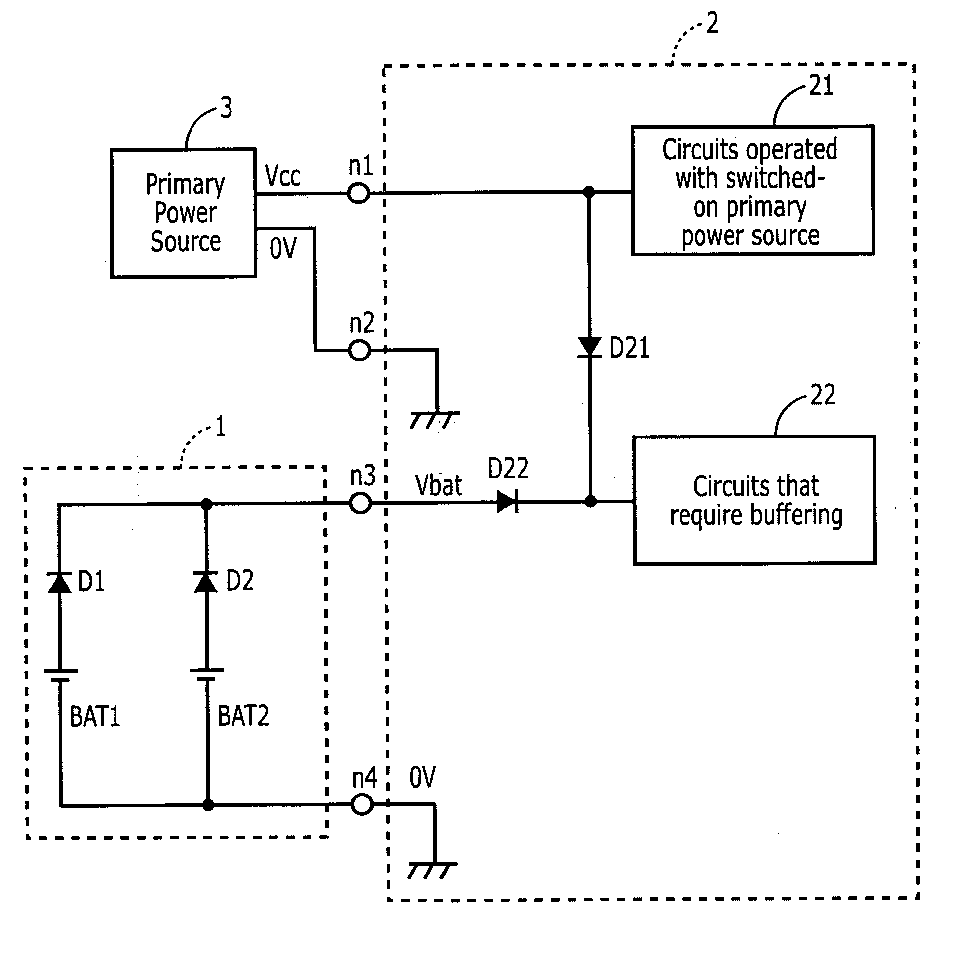
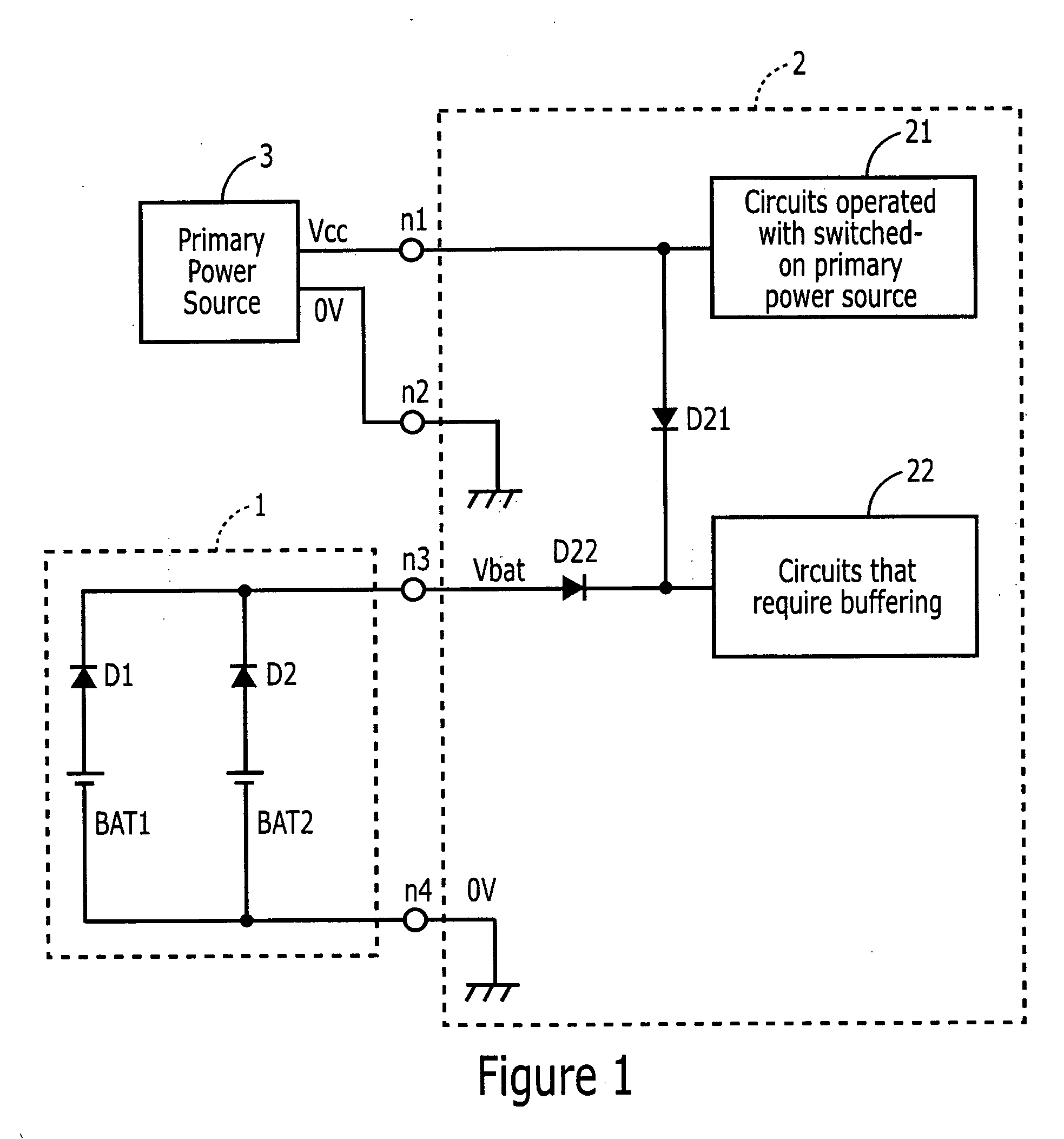
[0041]FIG. 1 is a circuit diagram that illustrates an example embodiment of the present invention. In the Figure, on the inside of encoder main part 2, there are circuits 21, which are operated when the main current source is switched on, and circuits 22 that need buffering, the respective currents of which are supplied by separate systems. That means, circuits 21, which are operated when the main current source is switched on, are connected via nodes n1 and n2 to a main current source 3, and are provided by main current source 3 with a current driven by a voltage Vcc. In this example embodiment, circuits 21, which are operated when the main current source is switched on, in the case of a multi-rotation absolute encoder, may be a circuit, for example, for determining the absolute position within one revolution, a processing circuit, an output circuit, etc., and the circuits 22 that require buffering may include a circuit for determining the data of the revolutions per time, a proces...
example embodiment 2
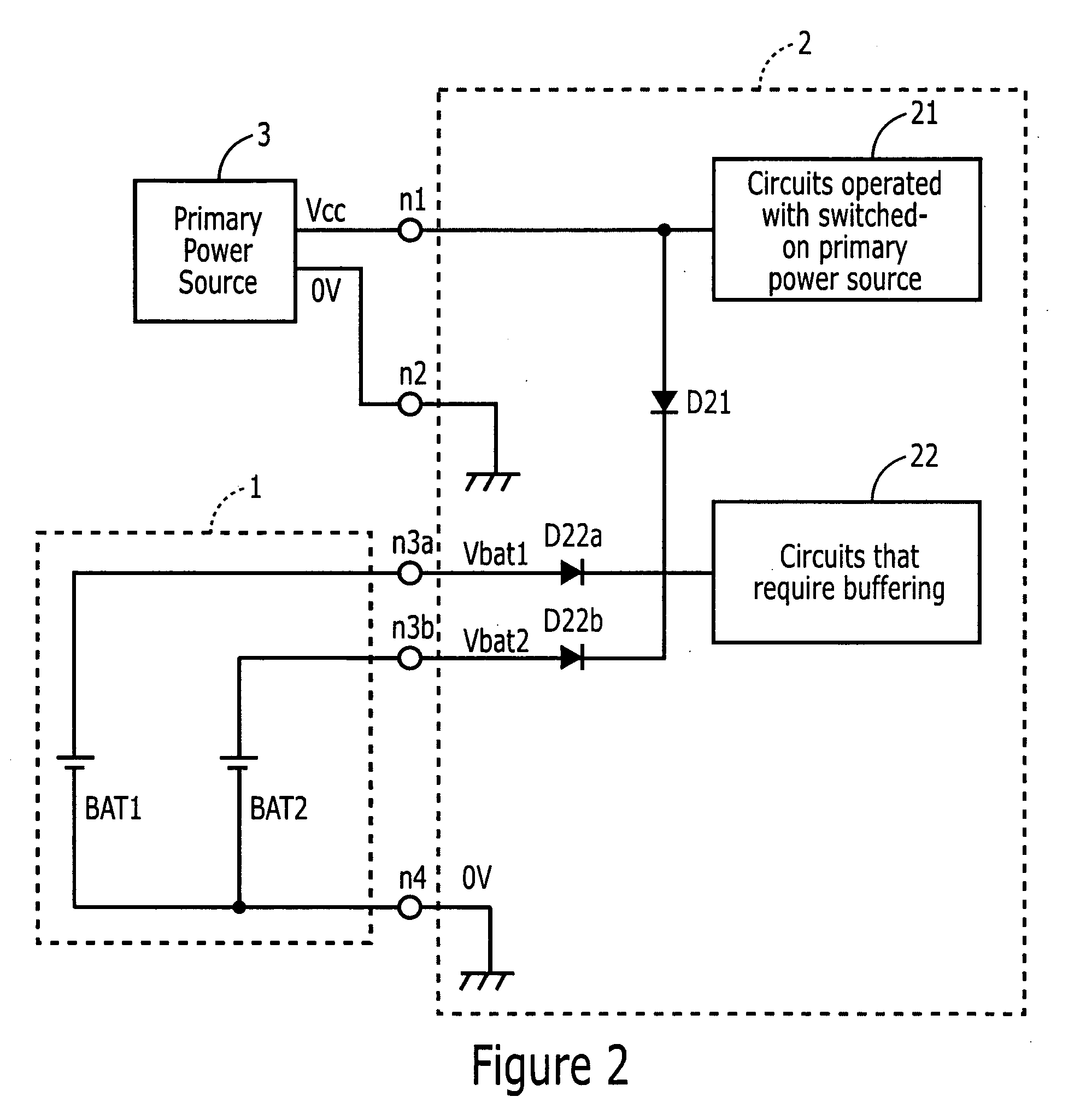
[0050]FIG. 2 is a circuit diagram which illustrates an example embodiment of the present invention. In the Figure, in backup current source 1 only one main battery BAT1 and one auxiliary current source BAT2 are provided. Node n3 of FIG. 1 is divided into a node n3a and a node n3b, which respectively connect main battery BAT1 and auxiliary battery BAT2. Diodes D22a and D22b are respectively connected to nodes n3a and n3b, which, in turn, are connected to the circuits that require buffering. This means that, by arranging diodes D1 and D2 of FIG. 1 on the inside of encoder main part 2, a diode OR circuit is formed, e.g., as in FIG. 1. Additional features correspond to those illustrated in FIG. 1. The same or similar features are provided with the same reference characters.
[0051] In this example embodiment, the number of terminals is been increased by the extent of the division by two of nodes n3 into a node n3a and a node n3b, but the number of diodes has been reduced by “one,” and th...
example embodiment 3
[0052]FIG. 3 is a circuit diagram that illustrates an example embodiment of the present invention. In the Figure, a main battery BAT1 and a capacitor Cb are arranged as an auxiliary current source in backup current source 1. Main current source 3 and capacitor Cb are connected via a diode D3, and when main current source 3 is switched on, current having a voltage Vcc is supplied, and capacitor Cb is charged.
[0053] The two ends of capacitor Cb are connected in parallel to the serial circuit of main battery BAT1 and of diode D1, and to nodes n3 and n4. That means that capacitor Cb is connected in place of battery BAT2 as auxiliary current source and of diode D2 of FIG. 1. Additional features correspond to those illustrated in FIG. 1. The same or similar features are provided with the same reference characters.
[0054] By using capacitor Cb as auxiliary current source, main battery BAT1 may consequently be exchanged, as with battery BAT2, even without the availability of a capacitor, e...
PUM
Abstract
In a position measuring device in which data, which requires buffering, may be held without accommodating a high-capacitancecapacitor in the inside of the encoder, a backupcurrent source may be exchanged while the circuits required for the operating capability state remain operable. In addition, current usage during the buffering time may be held low, and the service life of the backupcurrent source may be extended, so that the demand for maintenance may be reduced. The position measuring device may include an encoder main part, arranged to measure the extent of the shift in position of an object to be measured, and a backupcurrent source arranged to supply backup current when main current source, that supplies encoder main part with current, is interrupted. Outside of the encoder main part, an auxiliary current source is provided which, during the exchange of a main battery of the backup current source, undertakes supplying backup current in place of this main battery. The backup current source supplies backup current only to those circuits of the encoder main part which require buffering.
Description
CROSS-REFERENCE TO RELATED APPLICATIONS [0001] The present application claims priority to Japanese Patent Application No. 2004-032130, filed on Feb. 9, 2004, which is expressly incorporated herein in its entirety by reference thereto. FIELD OF THE INVENTION [0002] The present invention relates generally to a position measuring device. The present invention also relates to a backup current source of a position measuring device which is mounted on the rotor of, e.g., a motor, or on an object moving in a straight line that is to be measured, and determines the extent of the shift in position of the object to be measured, e.g., the revolutions per unit time and / or the angle of rotation or the position of motion, etc. BACKGROUND INFORMATION [0003] Position measuring devices, e.g., absolute position measuring devices, may have a backup current source in order to prevent the loss, in case of an interruption of the main current source, of data important for the operation of the encoder, suc...
Claims
Application Information
Patent Timeline
Application Date:The date an application was filed.
Publication Date:The date a patent or application was officially published.
First Publication Date:The earliest publication date of a patent with the same application number.
Issue Date:Publication date of the patent grant document.
PCT Entry Date:The Entry date of PCT National Phase.
Estimated Expiry Date:The statutory expiry date of a patent right according to the Patent Law, and it is the longest term of protection that the patent right can achieve without the termination of the patent right due to other reasons(Term extension factor has been taken into account ).
Invalid Date:Actual expiry date is based on effective date or publication date of legal transaction data of invalid patent.

