Plasma display panel

a technology of display panel and plasma, which is applied in the direction of gas-filled discharge tubes, gas exhaustion means, and electrodes, etc., can solve the problems of increasing the discharge error between neighboring discharge cells b>115/b>, affecting the brightness and image and affecting the discharge quality of the display panel. , to achieve the effect of improving brightness and image quality

Inactive Publication Date: 2005-12-29
PANASONIC CORP
View PDF6 Cites 12 Cited by
  • Summary
  • Abstract
  • Description
  • Claims
  • Application Information

AI Technical Summary

Benefits of technology

[0014] According to such a configuration, it becomes possible to realize a PDP capable of suppressing discharge error, releasing impurity gas from an inner space of the PDP and filling discharge gas into the inner space of the PDP, satisfactorily, this improving brightness and image quality.

Problems solved by technology

However, in this case, there may be a problem that discharge error between neighboring discharge cells 115 is increased.
In order to solve such a problem, it is thought that discharge error is suppressed by forming barrier ribs 112 in a lattice, which, however, may make it difficult to satisfactorily release impurity gas from an inner space of the PDP and to fill discharge gas into the inner space of the PDP.

Method used


Image

  • Plasma display panel
  • Plasma display panel
  • Plasma display panel

Examples


first exemplary embodiment

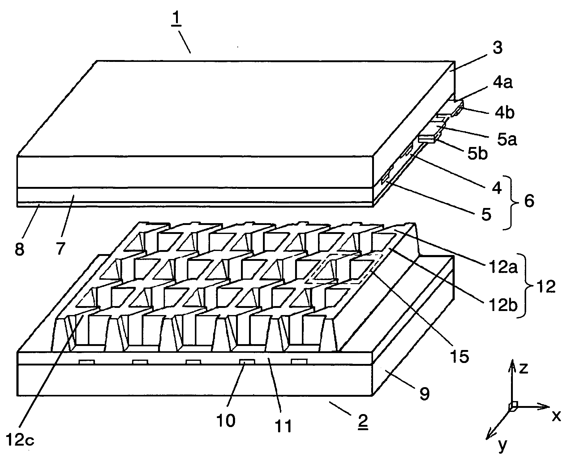
[0039]FIG. 1 is a perspective view showing a schematic configuration of a PDP according to a first exemplary embodiment of the present invention.

[0040] As shown in FIG. 1, a PDP according to the first exemplary embodiment includes front panel 1 and rear panel 2. Note here that in FIG. 1, for easy understanding of the structure, front panel 1 and rear panel 2 are drawn separately.

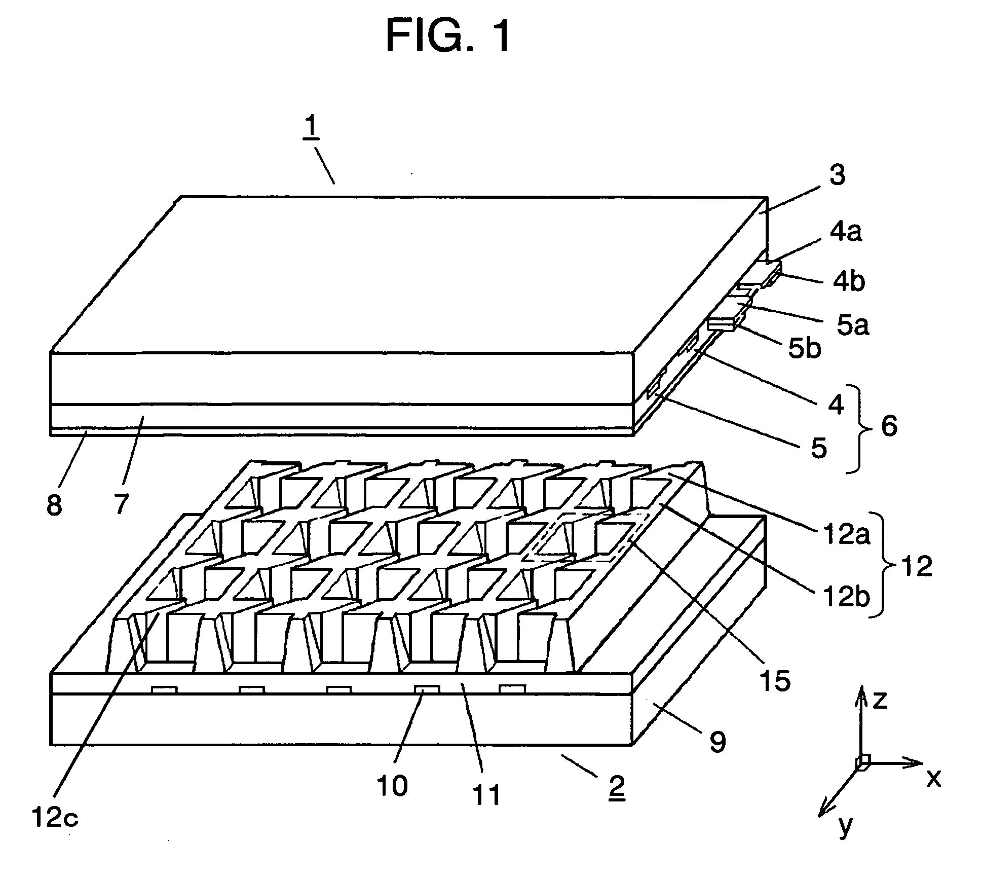
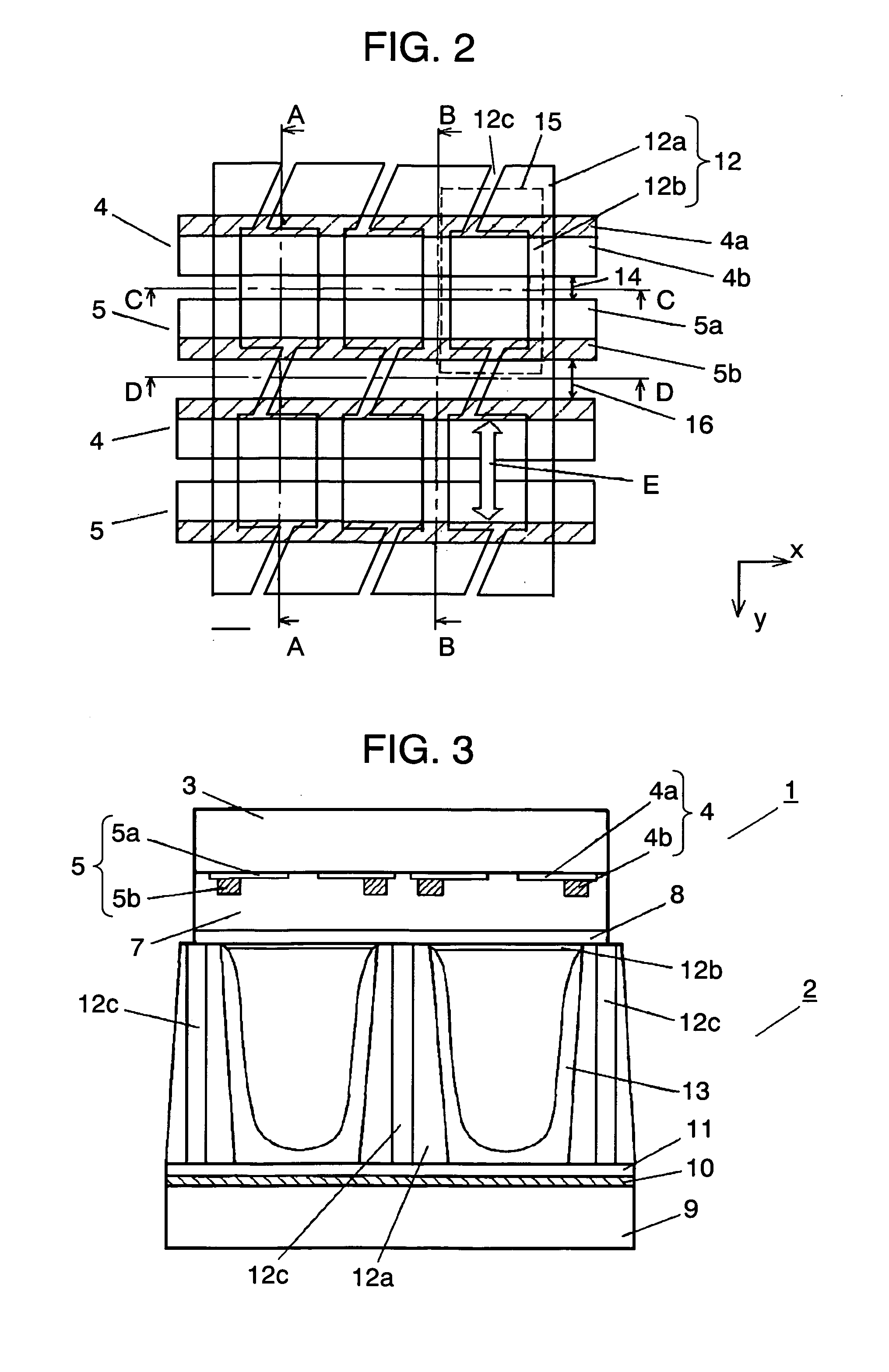
[0041] Front panel 1 includes plural pairs of stripe-shaped display electrodes 6 composed of scan electrode 4 and sustain electrode 5, extending in the row direction (in the direction of x in FIG. 1), on transparent front substrate 3 such as a glass substrate made of sodium borosilicate glass made by the floating method. Dielectric layer 7 is formed so as to cover a group of display electrodes 6. Protective film 8 made of MgO is formed on dielectric layer 7. Note here that scan electrode 4 and sustain electrode 5 are respectively composed of transparent electrodes 4a and 5a and bus electrodes 4b and 5b whi...

second exemplary embodiment

[0057]FIG. 10 is a perspective view showing a schematic configuration of a PDP according to a second exemplary embodiment of the present invention.

[0058] As shown in FIG. 10, the PDP according to the second exemplary embodiment includes front panel 21 and rear panel 22. Note here that in FIG. 10, for easy understanding of the structure, front panel 21 and rear panel 22 are drawn separately.

[0059] Plural pairs of stripe-shaped display electrodes 26 composed of scan electrode 24 and sustain electrode 25, extending in the row direction (in the direction of x in FIG. 10), are formed on transparent front substrate 23 such as a glass substrate made of sodium borosilicate glass made by the floating method. Dielectric layer 27 is formed so as to cover a group of display electrodes 26. Protective film 28 made of MgO is formed on dielectric layer 27. Thus, front panel 21 is configured. Note here that scan electrode 24 and sustain electrode 25 are respectively composed of transparent electro...


PUM


Abstract

A plasma display panel includes a front panel and a rear panel disposed opposing each other. The front panel includes a display electrode composed of a scan electrode and a sustain electrode extending in a row direction. A rear panel includes address electrode extending in a column direction and intersecting the display electrode. A lattice form of barrier ribs of row direction barrier ribs and column direction barrier ribs, which have the same height, forming a plurality of individually divided discharge cells is provided in a part in which the display electrode and the address electrode intersect each other. The row direction barrier ribs of the barrier ribs are provided with communication portions communicating discharge cells in non-parallel to the column direction.

Description

TECHNICAL FIELD [0001] The present invention relates to a plasma display panel known as a display device. BACKGROUND ART [0002] Recently, expectation for a large-screen wall-mount television set as a bi-directional information terminal has increased. Display devices therefor include many devices such as a liquid-crystal display panel, a field emission display, an electroluminescence display, and the like. Among these display devices, much attention has focused on a plasma display panel (hereinafter, referred to as “PDP”) as a thin display device excellent in visibility because it is a self light-emitting type display device capable of displaying beautiful images and realizing a large screen easily, etc. Development of higher definition and larger screen PDPs is under way. [0003] PDPs are roughly classified into AC type and DC type in terms of driving, and also classified into surface discharge type and opposing discharge type. For higher definition, larger screen and ease in manufac...

Claims


Application Information

Patent Timeline
Patent Type & Authority Applications(United States)
IPC IPC(8): H01J11/12H01J11/14H01J11/22H01J11/24H01J11/26H01J11/34H01J11/36H01J11/38
CPCH01J11/12H01J2211/361H01J11/36H01J11/54H01J11/34
Inventor FUJITANI, MORIO
Owner PANASONIC CORP
Why Eureka
Try Eureka