Method of recording data on optical recording media and optical recording device

a recording media and optical recording technology, applied in the field of optical recording media, can solve the problems of inability to solve the problem, loss of margins, and indistinct trailing edges of recording marks, and achieve the effect of preventing heat interference between consecutive recording marks and cross-erase between adjacent tracks

Inactive Publication Date: 2005-12-29
TDK CORPARATION
View PDF12 Cites 6 Cited by
  • Summary
  • Abstract
  • Description
  • Claims
  • Application Information

AI Technical Summary

Benefits of technology

[0027] According to the present invention, heat interference between consecutive recording marks and cross erase between adjacent tracks can be prevented when recording marks in an optical recording medium. The effect of preventing heat interference between recording marks and cross erase between adjacent tracks is particularly evident in a semi-transparent recording layer with a thin metal heat-sink layer.

Problems solved by technology

With conventional recording strategies, the trailing edges of recording marks tend to be indistinct because of heat accumulated in the recording layer before the last write pulse.
This approach is effective only to the limited extent with slow cooling structured recording layers and cannot solve the problem that various margins are lost.
This slow cooling structure brought about the problem of heat interference between consecutive recording marks and between adjacent tracks (so-called as cross erase), because the marks that were transformed into the amorphous state by rapid cooling are not cooled sufficiently quickly.
However, these methods require adjustment of laser pulse at an increased number of power levels, making the laser modulation process complicated.
In this case, however, the control of the mark length and width would be difficult, as the same number of write pulses are used to write marks with different lengths, e.g., m write pulses for both 2 mT mark and (2m+1)T mark.

Method used


Image

  • Method of recording data on optical recording media and optical recording device
  • Method of recording data on optical recording media and optical recording device
  • Method of recording data on optical recording media and optical recording device

Examples


first exemplary embodiment

[0036] A first exemplary embodiment of the present invention will be hereinafter described in detail with reference to FIG. 1 and FIG. 2.

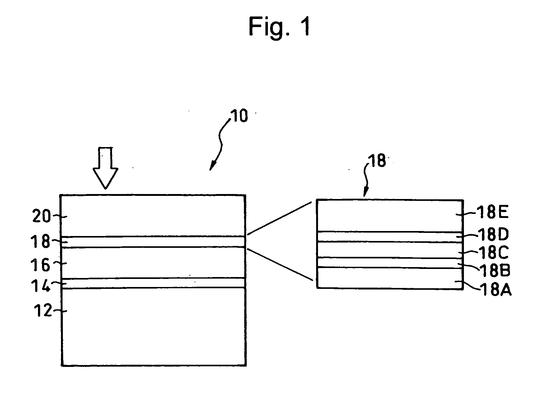
[0037] An optical recording medium 10 according to the first exemplary embodiment includes a first recording layer or L0 layer 14, a transparent intermediate layer 16, a second recording layer or L1 layer (hereinafter “recording layer”) 18, and a light transmitting layer 20 laminated on a substrate 12 in this order.

[0038] The recording layer 18 includes, as shown in enlargement in FIG. 1, an underlayer 18A on the transparent intermediate layer 16, a metal heat-sink layer 18B, a second protection layer 18C, a phase-change recording layer 18D, and a first protection layer 18E, laminated upon one another in this order.

[0039] The metal heat-sink layer 18B is provided for heat-sink and light interference and is made preferably of an Ag alloy. The layer thickness t is 018 has an overall light transmittance of 30% to 80% at a recording wavelength. The ...

example 1

[0059] Double-layer optical recording media similarly structured as the medium 10 of FIG. 1 were produced, and the recording / reproducing characteristics of their recording layers (L1 layers) were evaluated.

[0060] The followings are the attributes of the double-layer optical recording media:

[0061] Substrate thickness: 1.1 mm; Thickness of transparent intermediate layer: 25 μm; Thickness of light transmitting layer 75 μm; Material and thickness of phase-change recording layer in L1 layer: Sb eutectic alloy, 6 nm; Material and thickness of metal heat-sink layer: Ag alloy, 10 nm; Material of the 1st protection layer, 2nd protection layer, and underlayer: Laminated dielectric layers of AlN, ZnS—SiO2, and ZrO2; Thickness of 1st protection layer: 60 nm; Thickness of 2nd protection layer: 5 nm; Thickness of underlayer: 5 nm.

[0062] After making the L1 layer (phase-change recording layer) in the crystalline state using an initializing device (initialization), random signals were recorded w...

example 2

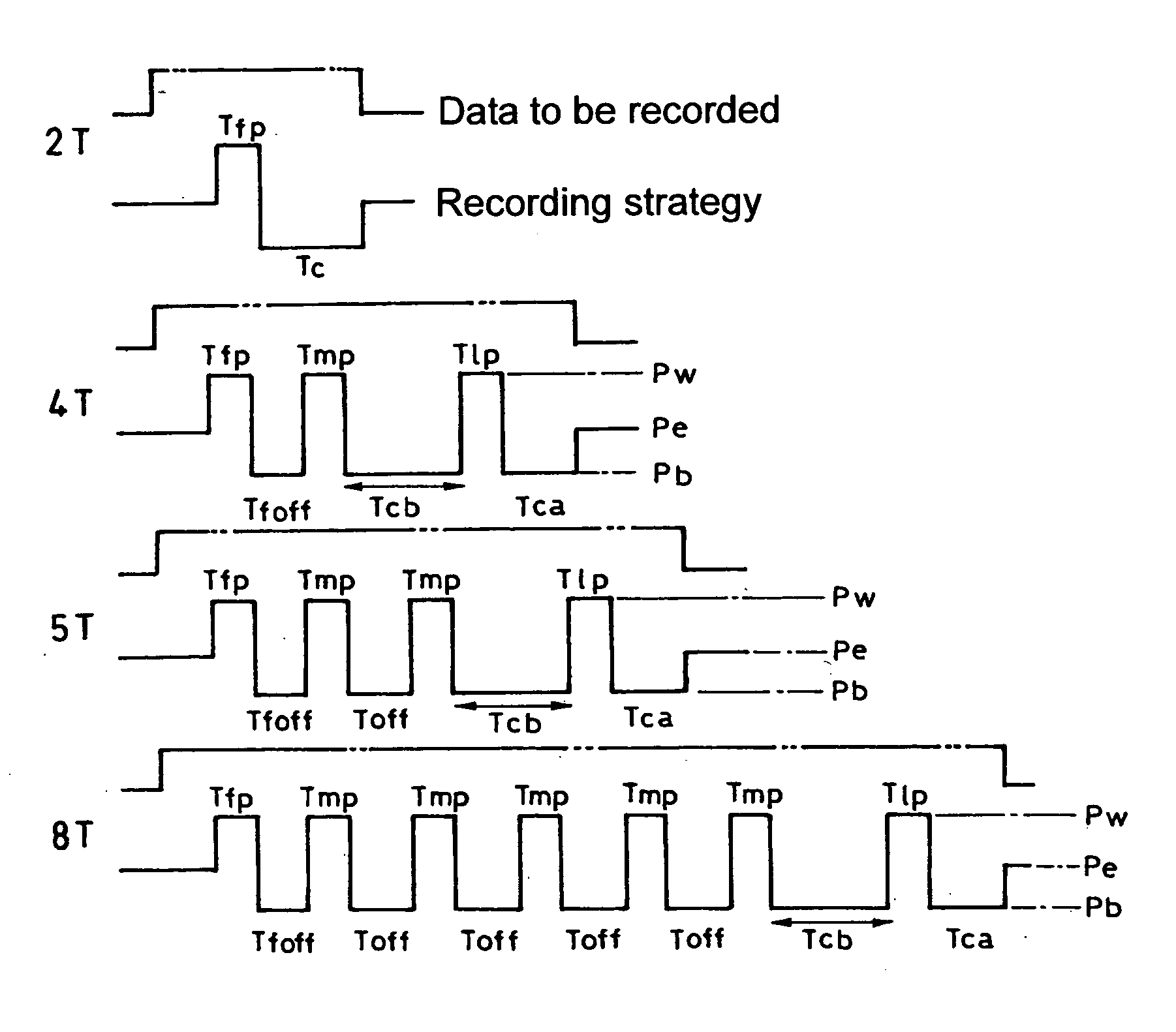
[0074] The clock jitter was measured during reproducing from the L1 layer of the double-layer optical recording media recorded in the same condition as in the example 1 except that the width of Tcb was varied sequentially (0.8T, 1.2T, 1.6T, 2.0T, and 2.4T) and the erase power Pe was varied between 2.6 mW and 5.5 mW. FIG. 7 and Table 1 show the measurement results thereof.

TABLE 1ConventionalStrategyTcb =Tcb =Tcb =Tcb =Tcb =Pe(Tcb = 0.7T)0.8T1.2T1.6T2.0T2.4T2.6Limit11.7511.6011.402.9−Jitter8.608.708.9010.1011.003.2(%)7.107.257.658.258.9012.203.57.006.907.157.458.0010.253.87.306.956.957.157.659.154.18.607.957.157.157.559.054.49.608.907.407.257.559.204.711.3010.208.007.807.959.805.012.059.409.008.7010.605.511.8011.2510.6512.10

[0075] These results show that, when the pulse width of the cooling pulse Tcb is set between 0.8T and 2.0T, the clock jitter is smaller in comparison with the cases where Tcb was set to 0.7T and 2.4T. Namely, this means the recording mark can be formed clear.

[00...


PUM

PropertyMeasurementUnit
light transmittanceaaaaaaaaaa
thickaaaaaaaaaa
thickaaaaaaaaaa

Abstract

A method of recording data on a double-layer optical recording medium having a recording layer with high light transmittance is provided. A laser beam is modulated to emit a pulse series of laser including a write pulse of a write power and a cooling pulse of a bottom power, so as to encode and write data to be recorded as recording marks of a length nT along a track of the recording layer, where n is an integer and T is one clock cycle. An nT recording mark is formed using (n-1) write pulse(s), and when forming a recording mark of 4 T or longer, a cooling pulse with a pulse width of 0.8 T to 2 T is inserted before the last write pulse. Recording marks are thereby accurately formed without heat interference between consecutive recording marks and cross erase between recording marks of adjacent tracks.

Description

BACKGROUND OF THE INVENTION [0001] 1. Field of the Invention [0002] The present invention relates to an optical recording medium having a semi-transparent recording layer, and a method and a device for recording data on the optical recording medium. [0003] 2. Description of the Related Art [0004] There are known double-layer phase-change optical recording media having two phase-change recording layers L0 (rear side layer) and L1 (front side layer). [0005] Optical recording media such as DVD (Digital Versatile Disc) use a modulation scheme to encode data to be recorded into recording marks along each track of the recording layer. The length of recording marks is nT, where n is an integer and T is one clock cycle. CD-RW (Compact Disc Rewritable), for example, uses the Eight-to-Fourteen Modulation (EFM) scheme to encode data to be recorded into recording marks with lengths ranging from 3 T to 11T. [0006] Rewritable optical recording media such as CD-RW and the like generally have a pha...

Claims


Application Information

Patent Timeline
Patent Type & Authority Applications(United States)
IPC IPC(8): G11B7/00G11B7/0045
CPCG11B2007/0013G11B7/00456
Inventor MIZUSHIMA, TETSUROKATO, TATSUYASHINGAI, HIROSHIMIURA, HIDEAKIYOSHINARI, JIRO
Owner TDK CORPARATION
Why Eureka
Try Eureka