
Determining a time difference between first and second clock domains

a clock domain and time difference technology, applied in the field of determining a time difference between different clock domains, can solve the problems of buffering delay of data word in the transmit buffer, buffering delay of data word in the receive buffer, etc., to achieve flexible and efficient product differentiation

Active Publication Date: 2005-12-29
TELEFON AB LM ERICSSON (PUBL)
View PDF7 Cites 72 Cited by
  • Summary
  • Abstract
  • Description
  • Claims
  • Application Information

AI Technical Summary

Benefits of technology

[0006] Efforts have been underway to provide a standardized common interface between a REC and one or more REs to enable flexible and efficient product differentiation for radio base stations and independent technology evolution for the RE and REC. One such standard is the Common Public Radio Interface (CPRI), and it defines necessary items for transport, connectivity, and control including user plane data, control and management (C&M) plane transport mechanisms, and synchronization. The CPRI interfaces carries timing information, IQ data samples, and operations and maintenance (O&M) link for communications between the REC and each RE. These three flows are multiplexed in a time division multiplex (TDM) frame structur

Problems solved by technology

The buffering of the data is associated with a buffering delay.
The buffering of the data word in the transmit buffer is associated with a transmit buffering delay.
The buffering of the data word in the receive buffer is associated with a receive buffering delay.

Method used


Image

  • Determining a time difference between first and second clock domains
  • Determining a time difference between first and second clock domains
  • Determining a time difference between first and second clock domains

Examples


Embodiment Construction

[0027] The following description sets forth specific details, such as particular embodiments, procedures, techniques, etc., for purposes of explanation and not limitation. But it will be appreciated by one skilled in the art that other embodiments may be employed apart from these specific details. For example, although the following description is facilitated using non-limiting examples, the present invention may be employed to in any type of radio communications system where base stations are used. In some instances, detailed descriptions of well-known methods, interfaces, circuits, and signaling are omitted so as not obscure the description with unnecessary detail. Moreover, individual blocks are shown in some of the figures. Those skilled in the art will appreciate that the functions of those blocks may be implemented using individual hardware circuits, using software programs and data, in conjunction with a suitably programmed digital microprocessor or general purpose computer, ...


PUM


Abstract

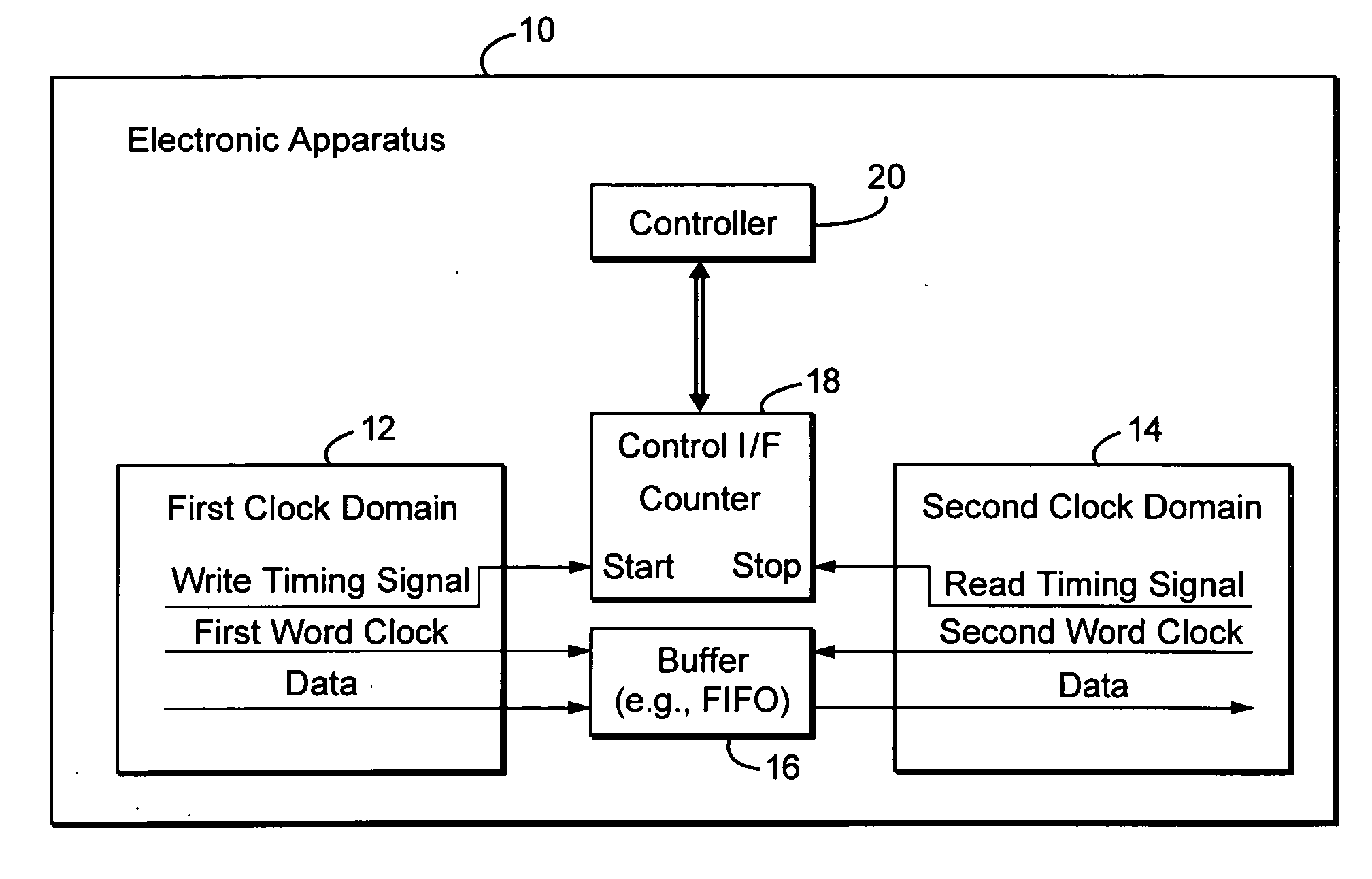
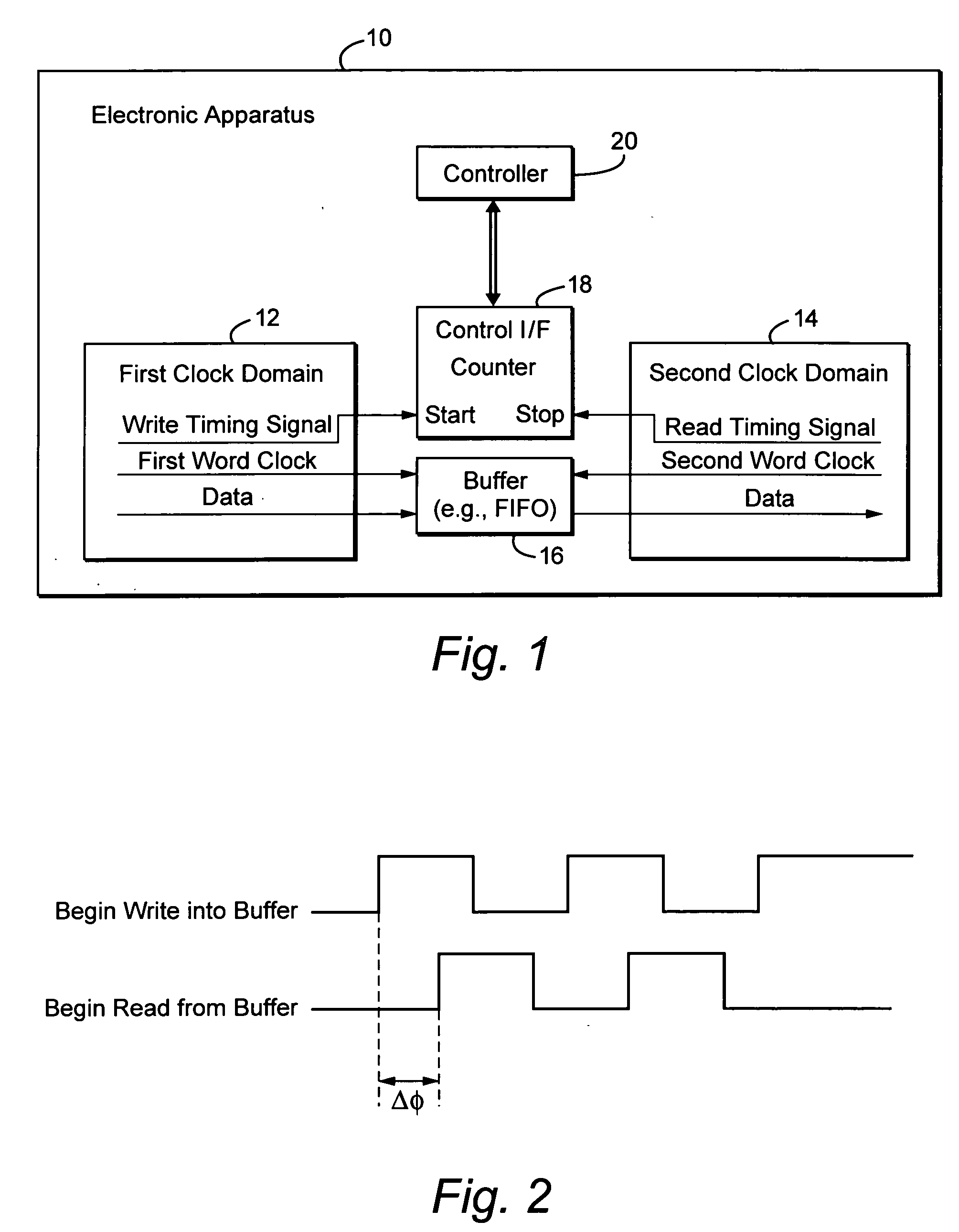
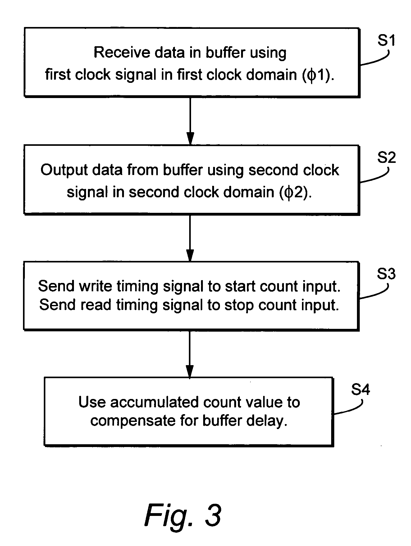
Buffer circuitry receives data to be processed by electronic circuitry using a first clock signal associated with a first clock domain. The buffered data is output using a second clock signal associated with a second clock domain. The buffering of the data is associated with a buffering delay. Counting circuitry receives at a start count input a write timing signal associated with the first clock domain and with writing data to the buffer circuitry. The counting circuitry receives at a stop count input a read timing signal associated with the second clock domain and with reading data from the buffer circuitry. A count value accumulated between receiving the write timing signal and the read timing signal corresponds to the buffering delay. Control circuitry performs a control operation based on the count value.

Description

RELATED APPLICATION [0001] This application claims priority from U.S. provisional application No. 60 / 573,338, filed on May 24, 2004, entitled “CPRI SERDES Timing,” the contents of which is incorporated herein by reference. In addition, the application is related to co-pending PCT application PCT / IB2004 / 003170, entitled “Interface, Apparatus, And Method For Communication Between A Radio Equipment Control Node And A Remote Radio Equipment Node In A Radio Base Station,” filed on Sep. 29, 2004, the contents of which is incorporated herein by reference.TECHNICAL FIELD [0002] The technical field relates to determining a time difference between different clock domains. One example situation is communications between first and second processing circuits either on the same integrated circuit or on different integrated circuits. One of the two processing circuits could be a serializer / deserializer (SERDES) and the other an application specific integrated circuit (ASIC). Such may arise in many...

Claims


Application Information

Patent Timeline
IPC IPC(8): H04J3/06H04L7/02H04L12/50H04Q11/00
CPCH04J3/0605H04L7/005H04J3/0647H04L7/02
Inventor STERLING, JACOBAARFLOT, TORBJORN
Owner TELEFON AB LM ERICSSON (PUBL)
Learn More