Network connection system

a network connection and connection system technology, applied in the field of connecting devices, can solve the problems of large time and effort spent on troubleshooting and fixing inadequate field made connections, failure to transmit data, and failure to terminate all connections

Inactive Publication Date: 2005-12-29
CARROLL JAMES A
View PDF45 Cites 39 Cited by
  • Summary
  • Abstract
  • Description
  • Claims
  • Application Information

AI Technical Summary

Benefits of technology

[0020] The third advantage to the UCT connection has to do with the spatial orientation and configuration of the cable pairs. In typical industry standard IDC terminations, there are recommendations for managing the cable conductor pairs, however there is little or no control over the craft person's management of the conductor pair twist and spatial orientation of the conductor pairs as they are terminated to the jack IDC's. Both have impact on

Problems solved by technology

Problems are associated with installing jacks and plugs in the field related to inconsistency of method that occur from one installer to the next.
These result is failures in data transmission and the expenditure of large amounts of time and effort to troubleshoot and repair inadequate field made connections.
The obstacle to pre-terminating all connections lies in the need to feed a

Method used


Image

  • Network connection system
  • Network connection system
  • Network connection system

Examples


Embodiment Construction

[0068] Referring to FIGS. 1-47, the network connection system 100 includes universal cable termination (UCT) connector 102 and connecting hardware 104 as well as a dust cover 106, a pull ring cover 108 and a feeder strip 110.

[0069] The UCT connector 102, as depicted in FIGS. 11 and 16, generally includes strain relief boot 112, pair manager tray 114, pair manager cap 116, connector housing 118 and termination contacts 120. Two UCT connectors 102 along with an intervening cable connecting them are primarily intended as a station connector to connect from, for example, a switch panel to a jack. The jack is then connected to a peripheral such as a personal computer or a printer by a patch cable. Under applicable standards the station cable can extend up to three hundred twenty-seven feet.

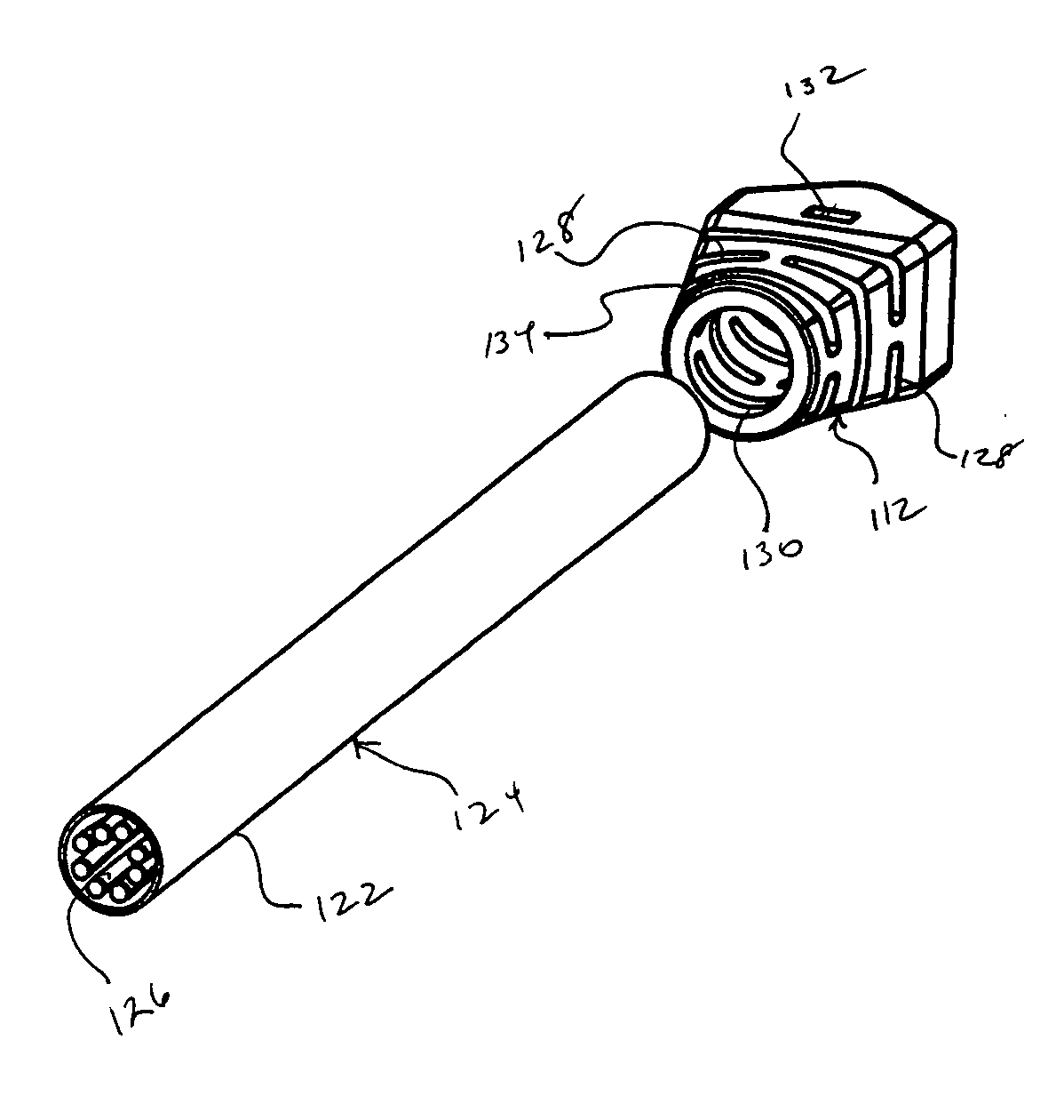
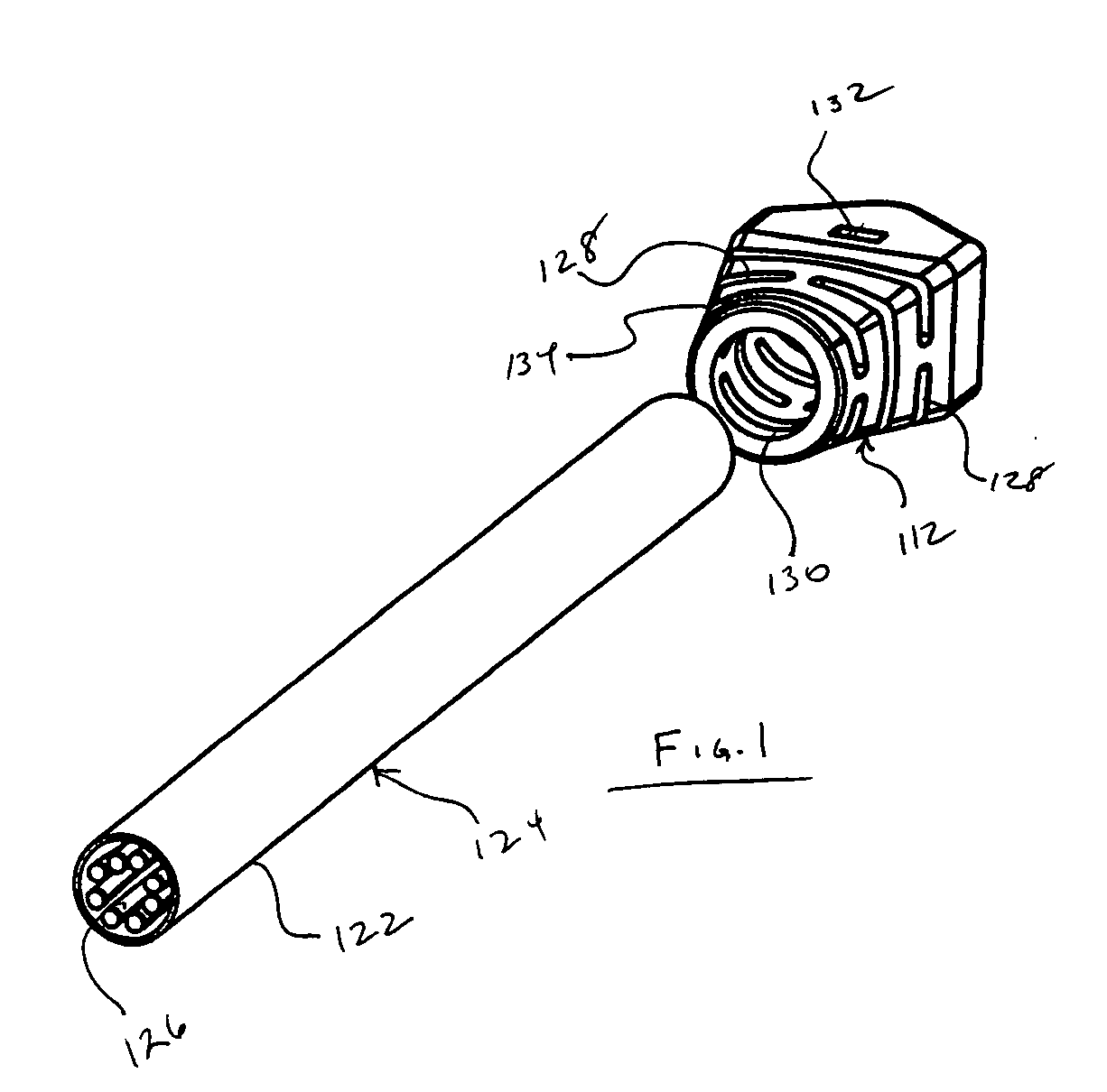
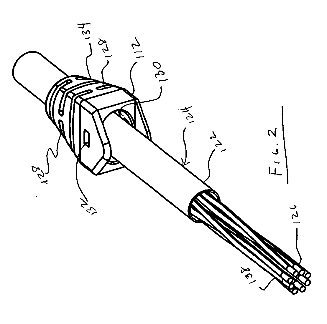
[0070] Referring FIGS. 1 and 2, to strain relief boot 112 is fabricated from a flexible polymer that slides with some resistance over the outer jacket 122 of cable 124 when assembled. The outer jacke...


PUM


Abstract

A network connection system for connecting computer network components, the network connection system including a twisted pair cable having multiple conductors in twisted pairs a cable termination connector affixable at an end of the cable. The cable termination connector includes a slender elongate connector housing; and termination contacts located within the connector housing. The termination contacts include a conductor engaging portion, optionally, an RJ connector engaging portion and a male contact portion releasably engageable to a female gripping contact. The network connection system also includes connecting hardware as well as a dust cover, a pull ring cover and a feeder strip. The present invention can be used on a local area network (LAN) or a wide area network (WAN).

Description

CLAIM TO PRIORITY [0001] This application claims priority to U.S. Provisional Application Ser. No. 60 / 582,404 filed Jun. 24, 2004 entitled “Twisted Pair Connection System and Method which is incorporated herein in its entirety by reference.FIELD OF THE INVENTION [0002] The invention generally relates to connectors for wiring computer and telephone networks. More particularly, the invention relates to connectors for termination twisted pair cables. BACKGROUND OF THE INVENTION [0003] Twisted pair cables are commonly used for the wiring of computer and telephone networks. Twisted pair wire orientation is governed by EIA / TIA Standard 568B and industry connection methods [0004] Conventional twisted pair cable includes four twisted pair conductors inside an outer insulation jacket. In some cables a plastic cross shaped extrusion resides inside the cable jacket along with the wires to separate the four pairs from each other and maintain each pair within its own quadrant within the cable ja...

Claims


Application Information

Patent Timeline
IPC IPC(8): H01R4/24H01R13/506H01R24/00H01R24/58
CPCH01R4/2404H01R13/506H01R13/585H01R24/64H01R2201/06Y10S439/941H01R13/6463H01R2201/04
Inventor CARROLL, JAMES A.FINKE, THOMAS R.
Owner CARROLL JAMES A
Why Eureka
Try Eureka