RF-based antenna selection in MIMO systems

a technology of antenna selection and mimo technology, applied in the field of selecting antennas, can solve the problems of increasing system and hardware complexity of multi-output (mimo) systems, high cost of chains, and prohibitive signal processing for systems with a large number of antenna elements, so as to increase the bandwidth of a wireless communication channel and reduce the complexity of the system

Inactive Publication Date: 2005-12-29
MITSUBISHI ELECTRIC RES LAB INC
View PDF4 Cites 169 Cited by
  • Summary
  • Abstract
  • Description
  • Claims
  • Application Information

AI Technical Summary

Benefits of technology

[0038] The invention increases the bandwidth of a wireless communications channel by employing multiple antenna elements at a transmitter and at a r

Problems solved by technology

However, an important factor limiting multiple input, multiple output (MIMO) systems is the increased system and hardware complexity.
These chains are expensive.
Furthermore, the sophisticated signal processing required for realizing the high rates achievable by MIMO techniques can be prohibitive for systems with a large number of antenna elements.
Given sufficient RF chains, antenna selection at the receiver does not reduce the diversity gain of the MIMO system.
However, it does lead to a loss in the coding gain.
Another issue is that considerable signal processing power is still required to implement a method that selects the best L out of Nr received signals.
Antenna selection therefore requires continuous monitoring and ranking of the channel coefficients in real-time, which is a complex task.
The complexity of the antenna selection process depends on the number of possibilities that need to be examined.
Reducing the number of possi

Method used


Image

  • RF-based antenna selection in MIMO systems
  • RF-based antenna selection in MIMO systems
  • RF-based antenna selection in MIMO systems

Examples


Embodiment Construction

[0057] System and Channel Model

[0058] Our invention provides a system and method for RF pre-processing and selecting a subset of the processed outputs in a multiple-input, multiple-output (MIMO) wireless communication system subject to spatially correlated MIMO channel conditions. Our invention is applicable to a general multiple antenna system that uses multiple antennas at the transmitter or at the receiver, or both.

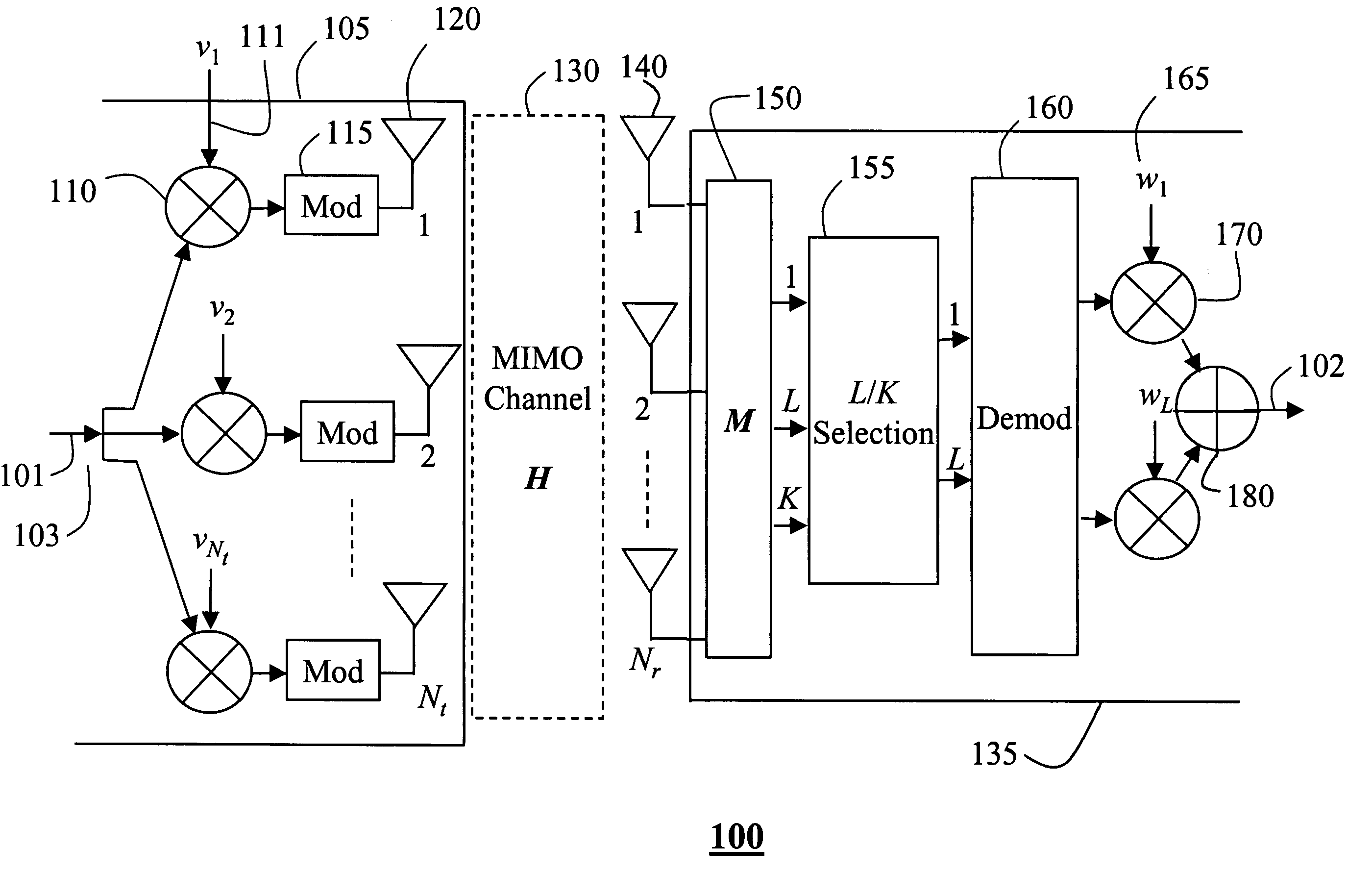
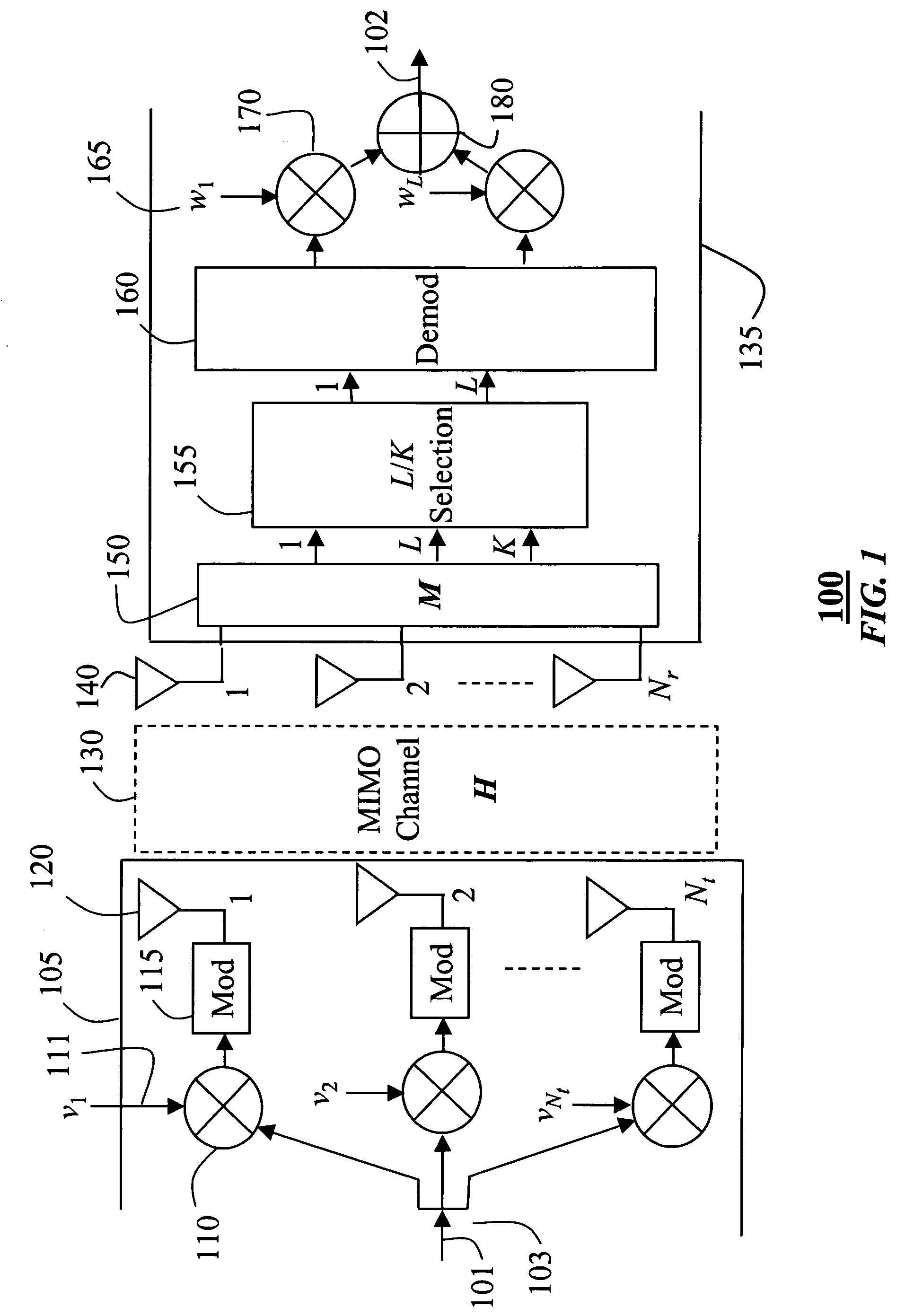
[0059] Specifically, the invention generates a matrix M based on long-term characteristics of the wireless channel. The matrix M is multiplied times input RF signals to obtain output RF signals. The matrix can be generated in a transmitter, a receiver, or both.

[0060]FIG. 1 shows a system 100 that can use our invention to maximize diversity gain. In a transmitter 105, partially shown, copies of an input signal stream 101 are multiplied 110 by an Nt-dimensional complex weighting vector v 111 before modulation 115 to passband. Each signal is then applied to a different...


PUM


Abstract

A method is presented for processing signals of a multiple-input, multiple-output communications system in the RF domain. The system includes multiple transmit antennas and multiple receive antennas connected by a wireless channel. A matrix M is generated based on long-term characteristics of the wireless channel. The matrix M is multiplied times input RF signals to obtain output RF signals. The matrix can be generated in a transmitter, a receiver, or both.

Description

FIELD OF THE INVENTION [0001] This invention relates generally to multiple-input, multiple-output communications systems, and more particularly to selecting antennas in such systems. BACKGROUND OF THE INVENTION [0002] The bandwidth of a wireless communications channel can be increased significantly by employing multiple antenna elements (MAE) at a transmitter and a receiver, Foschini et al., “On the Limits of Wireless Communications in a Fading Environment When Using Multiple Antennas,” Wireless Pers. Commun., Vol. 6, No. 3, pp. 311-335, March 1998. [0003] Multiple antennas can improve bit rates using spatial multiplexing, where different data streams are transmitted by each antenna, or enhance the diversity of the channel, where copies of the same data stream are transmitted on all of the antennas, Foschini, “Layered Space-Time Architecture for Wireless Communication in a Fading Environment When Using Multiple Antennas,” Bell Labs. Tech. J., vol. 1, no. 2, pp. 41-59, 1996, and Taro...

Claims


Application Information

Patent Timeline
IPC IPC(8): H01Q3/26H04J99/00H04B7/04H04B7/06H04B7/08H04L1/00H04L1/06
CPCH01Q3/26H04B7/0417H04B7/0626H04B7/0691H04L1/0631H04B7/0848H04B7/0874H04L1/0036H04L1/0625H04B7/0697
Inventor MEHTA, NEELESH B.SUDARSHAN, PALLAVMOLISCH, ANDREAS F.ZHANG, JINYUN
Owner MITSUBISHI ELECTRIC RES LAB INC
Why Eureka
Try Eureka