
Electronic endoscope system for fluorescence observation

a fluorescence observation and endoscope technology, applied in the field of electronic endoscope systems, can solve the problems of long fixed time period, inability to move the endoscope tip and observe other parts during the time period, and inability to display both kinds of images simultaneously as moving images

Inactive Publication Date: 2005-12-29
HOYA CORP
View PDF12 Cites 51 Cited by
  • Summary
  • Abstract
  • Description
  • Claims
  • Application Information

AI Technical Summary

Benefits of technology

[0009] The present invention is advantageous in that an electronic endoscope system is provided that is capable of displaying a normal image as a moving image immediately after displaying a still fluorescence image when an operator observing a moving fluorescence image operates the endoscope system to display the still fluorescence image.
[0018] Still optionally, the endoscope may include an objective lens that is provided to the insertion part, and an excitation light cut filter that is provided between the objective lens and the imaging device, the excitation light cut filter eliminating the wavelength components equivalent to the excitation light from light directed to the imaging device from the objective lens.
[0024] Furthermore, the endoscope may include an objective lens that is provided to the insertion part, and an excitation light cut filter that is provided between the objective lens and the imaging device, the excitation light cut filter eliminating the wavelength components equivalent to the excitation light from light directed to the imaging device from the objective lens.

Problems solved by technology

However, it takes such a long fixed period of time (t seconds) for the mirror 128 to turn and return that both kinds of images cannot be displayed simultaneously as moving images.
Therefore, it is impossible to move an endoscope tip and observe other parts during the time period.

Method used


Image

  • Electronic endoscope system for fluorescence observation
  • Electronic endoscope system for fluorescence observation
  • Electronic endoscope system for fluorescence observation

Examples


Embodiment Construction

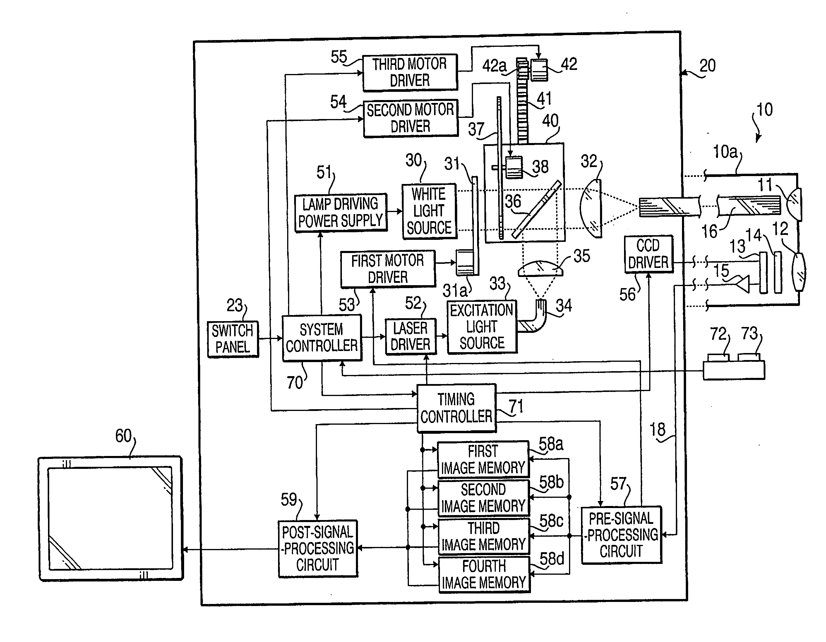
[0038] Hereinafter, an electronic endoscope system according to an embodiment of the present invention will be described with reference to the accompanying drawings. The electronic endoscope system of the embodiment is directed to a system that is adapted to observe a fluorescence image of autofluorescence emitted from a body cavity wall irradiated with excitation light on a display device such as a monitor, as well as a normal image of the body cavity wall illuminated with white light.

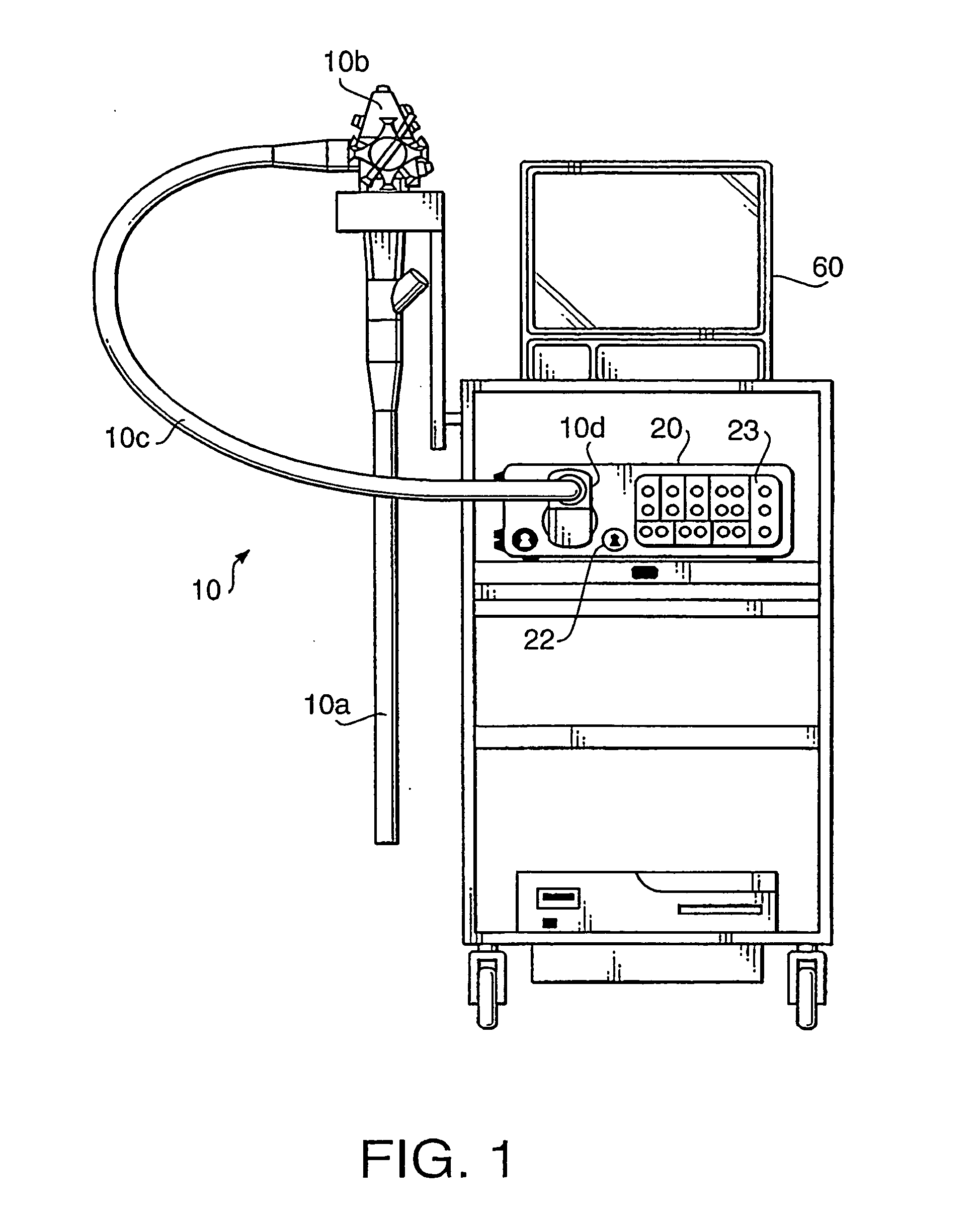
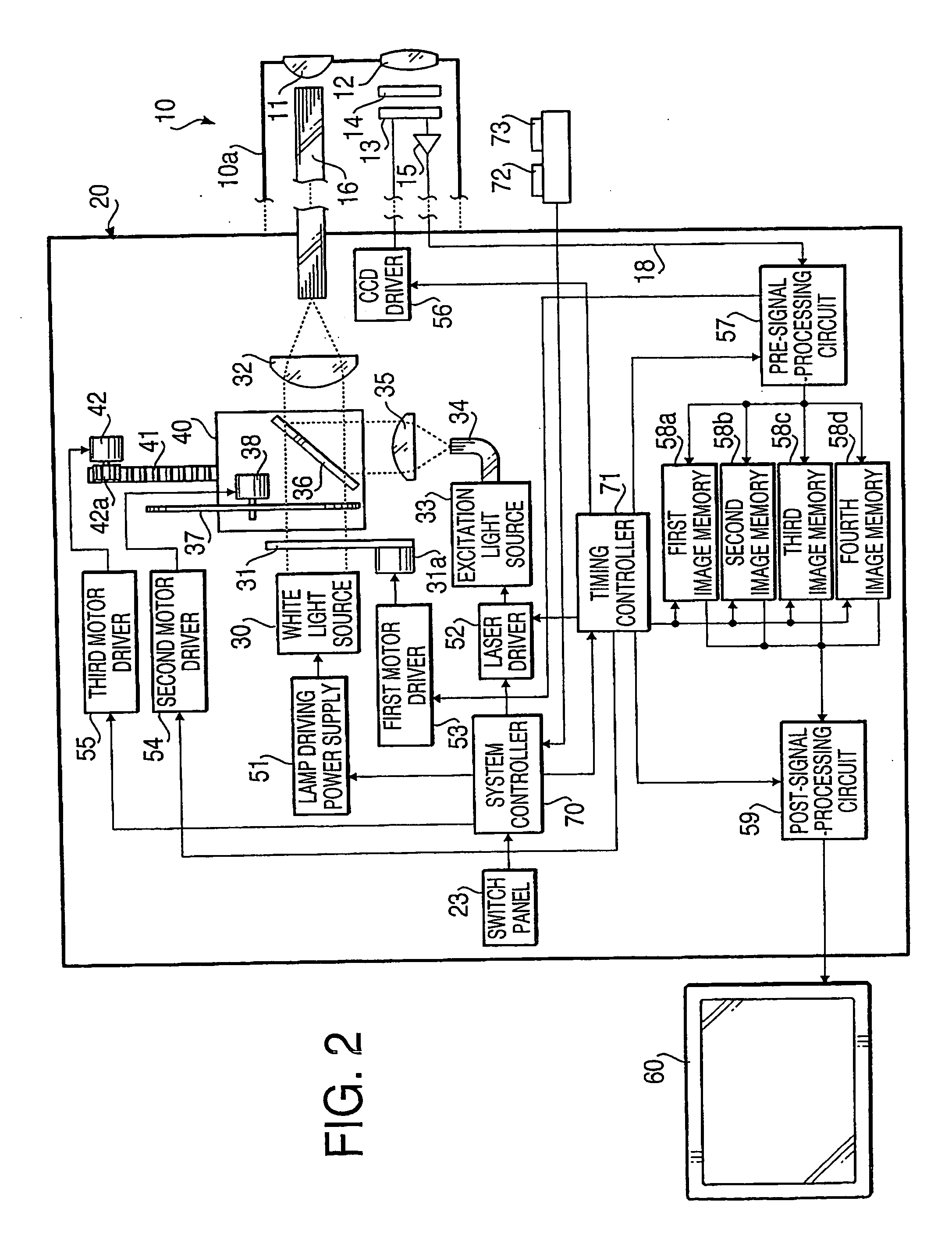
[0039]FIG. 1 schematically shows an external view of an electronic endoscope system 1 according to an embodiment of the invention, and FIG. 2 shows a block diagram illustrating an internal constitution of the electronic endoscope system 1. As shown in FIG. 1, the electronic endoscope system 1 is provided with a fluorescence observation endoscope 10, a light source apparatus 20, and a monitor 60.

[0040] The fluorescence observation endoscope 10, which is adapted to fluorescence observation by modifyin...


PUM


Abstract

An electronic endoscope system, which is adapted to observe a fluorescence image of autofluorescence emitted from a body cavity wall irradiated with excitation light, includes a controller that controls a light source apparatus to alternately introduce either white light or excitation light into a light guide while taking a normal color image and the fluorescence image, and controls an image signal generating system to generate normal color image signals and fluorescence image signals. The controller further controls a display device to display a still fluorescence image in a first window defined on a displaying area thereof based on the fluorescence image signals which have been generated when a still image switch is turned ON during the time to take the fluorescence image, and simultaneously to display a moving normal color image in a second window defined on a displaying area thereof based on the normal color image signals generated every time the body cavity wall is intermittently illuminated with the white light, the first window being larger than the second window.

Description

BACKGROUND OF THE INVENTION [0001] The present invention relates to an electronic endoscope system that is adapted to observe a fluorescence image of autofluorescence emitted from a body cavity wall irradiated with excitation light, as well as a normal image of the body cavity wall illuminated with white light, on a display device such as a monitor. [0002] An example of such an electronic endoscope system is disclosed in Japanese Patent Provisional Publications No. HEI 9-066023. The system disclosed in this publication includes a first solid-state imaging device for capturing a fluorescence image, and a second solid-state imaging device for capturing an RGB color image in accordance with a frame sequential method. In the system, signals outputted from the first and second solid-state imaging devices are processed by a video circuit for fluorescence images and a video circuit for normal images. The signals are then synthesized by an image synthetic circuit, and are displayed on a mon...

Claims


Application Information

Patent Timeline
Patent Type & Authority Applications(United States)
IPC IPC(8): A61B1/06A61B5/00
CPCA61B1/00009A61B1/0005A61B1/043A61B1/0646A61B5/0071A61B5/0084A61B1/00186A61B1/0638A61B1/0655
Inventor SUGIMOTO, HIDEO
Owner HOYA CORP
Learn More