[0013] A torque transmitting unit having an actuating device that is electrohydraulic may therefore be advantageous. At least one actuating device may be formed of a hydraulic
transmitter unit operable by means of an
electric motor, comprising a
piston / cylinder unit, at least one hydraulic
receiver unit applying pressure axially on the corresponding operating bearing, comprising a
piston / cylinder unit, and a pressure medium line connecting the
transmitter unit and the
receiver unit. The
receiver unit may have a plurality of sub-units positioned around at least one transmission input shaft, distributed around the circumference, to apply pressure to an operating bearing; to apply pressure to both friction clutches, both receiver units may have sub-units distributed around the circumference, and these may be distributed alternately around the circumference and positioned at approximately the same circumference. Alternatively, a receiver unit for a friction clutch may consist of a pressurizable ring cylinder with a ring piston that is axially movable in it, where two receiver units placed one over the other are able to operate one friction clutch. An arrangement in which an outer ring cylinder is supported on a radially inner ring piston in a manner that forms a seal, so that it is directly axially displaceable, may be especially advantageous, with separate pressure chambers being provided for the two pistons so that the two clutches may be operated independently of each other.
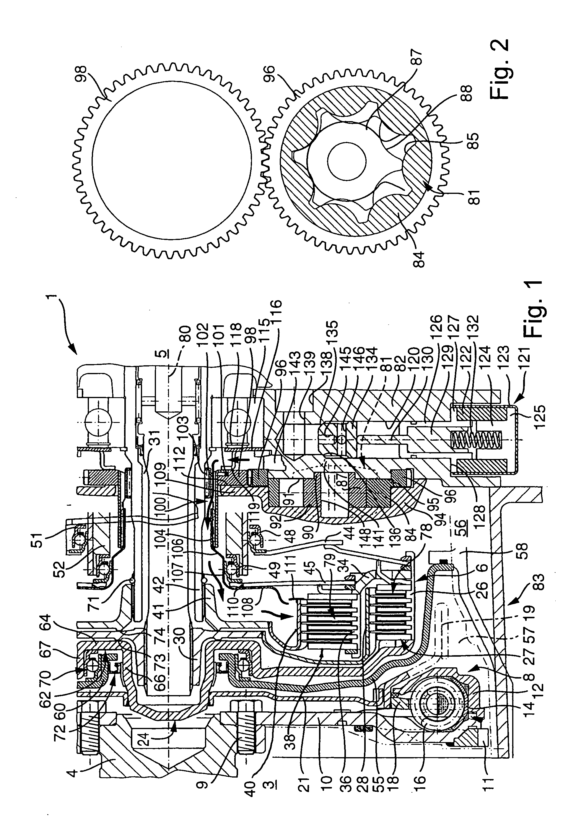
[0018] The internal
gear pump may be driven by means of a ring gear with an internal tooth
system, where the internal tooth
system meshes with an external tooth
system of a sun gear and a suction crescent is provided to draw the
coolant. In an advantageous manner, the sun gear may be supported radially by means of its external tooth system on a complementary segment of the suction crescent, so that separate support of the sun gear is unnecessary. Optionally, the use of a
gerotor pump may also be advantageous. To minimize the energy need of the pump, its volumetric flow may be regulated by means of suction throttling, where the suction throttling may be achieved by means of an
electromagnetic valve. In this way, up to a specified speed of rotation the volumetric flow for example may be proportional to the drive speed, and above a limiting speed it may be held at a constant value. Experimental values have shown that restricting the
coolant pressure to 5 bar, preferably 3 bar, and a maximum volumetric flow of 36 I / min, preferably 24 I / min, may be advantageous. In an advantageous manner, an oil cooler may be connected between the pump and the friction units of the friction clutches. The
coolant may escape into the
sump through an appropriate opening in the chamber, while it may be advantageous to capture coolant that has been forced radially outward as a result of the effect of
centrifugal force, using a dipping tube that is rigidly attached to the housing, and to guide it into the
sump. A dipping tube of this sort may be combined advantageously with other functional elements into a
single component, for example a receiver unit.
[0021] To reduce or eliminate torsional vibrations introduced into the transmission from the combustion engine, a dual
mass flywheel positioned between the crankshaft and the input part of the two friction clutches may be provided at the torque transmitting unit. This dual
mass flywheel may be integrated into the liquid-filled chamber (530, 630), or may be located outside the chamber. In addition, the dual
mass flywheel may form part of the housing for the chamber and / or may have a drive part for the pump. The dual mass flywheel may be mounted on the crankshaft by means of an axially flexible disk part, a so-called “flexplate.” Of course, the torque transmitting unit may also be mounted on the crankshaft in this way without a dual mass flywheel. It can be especially advantageous in connection with the mass conditions of a double clutch with wet clutches to design two masses that are relatively rotatable with respect to at least one
energy storage device that acts in the circumferential direction so that they may be coupled together at least temporarily, the
coupling being achievable by mean of a friction device that depends on
centrifugal force. The use of a
coupling may be especially advantageous with the following mass conditions: a first mass, coupleable on the drive side, has a
moment of inertia of 0.1±0.04 kgm2, and a second mass on the drive side has a
moment of inertia of 0.04 to 0.08 kgm2. It has also proven advantageous to maintain the
coupling of the two masses up to a range of 1,200 to 1,800
revolutions per minute.
[0022] The torque transmitting unit may be installed by mounting the complete component with receiver unit and with dual mass flywheel, if used, on the transmission shafts of the double clutch transmission, and connecting it with a rotationally fixed connection to an axially flexible drive component which is connected to the crankshaft, such as a “flexplate,” when joining the combustion engine and the transmission. It may also be advantageous to connect parts of the dual mass flywheel, or the entire dual mass flywheel, to the crankshaft separately from the clutch unit, and to use connecting elements such as plug-in connections which permit axial movability and rotationally fixed connection of the connected parts to produce a connection between the combustion engine and the transmission. For purposes of guiding the torque transmitting unit, there may be a
pilot bearing on the latter by means of which the torque transmitting unit is rotatably mounted on the crankshaft. It may also be advantageous to support the torque transmitting unit on the crankshaft axially, for example by means of a slide bearing. It may be especially advantageous when installing the torque transmitting unit to adjust it or its movable components axially only roughly, to connect the actuating device to the transmission housing with a rotationally fixed connection, but so that it can move laterally, and when operating the torque transmitting unit for the first time to move it to its final position by means of self-adjusting, axially operating pressure of the transmission oil (ATF) on the axially movable components, for example by having them run into appropriately positioned stops.
[0032] Another preferred exemplary embodiment of the torque transmitting unit is characterized in that the
stream of coolant is conducted through a through hole in the sun gear of the pump. That provides a simple means of filling the pump on two sides, and the pump may be filled well in the non-suction-regulated state with the necessary cooling of the clutch.

