Force sensor and motor-driven parking brake apparatus using the same

Inactive Publication Date: 2006-01-05
ADVICS CO LTD
View PDF10 Cites 15 Cited by
  • Summary
  • Abstract
  • Description
  • Claims
  • Application Information

AI Technical Summary

Benefits of technology

[0009] The present invention has been accomplished in order to solve the problems in conventional force sensors, and an object of the present invention is to pro

Problems solved by technology

Therefore, although at the beginning of actual use of the sensor the point in time at which release of the above-mentioned force is completed can be detected accurately, in an intermediate or late stage of use, the point in time at which release of the above-mentioned force is completed cannot be detected accurately.
Moreover, in the motor-driven parking brake apparatus using a force sensor

Method used


Image

  • Force sensor and motor-driven parking brake apparatus using the same
  • Force sensor and motor-driven parking brake apparatus using the same
  • Force sensor and motor-driven parking brake apparatus using the same

Examples


Example

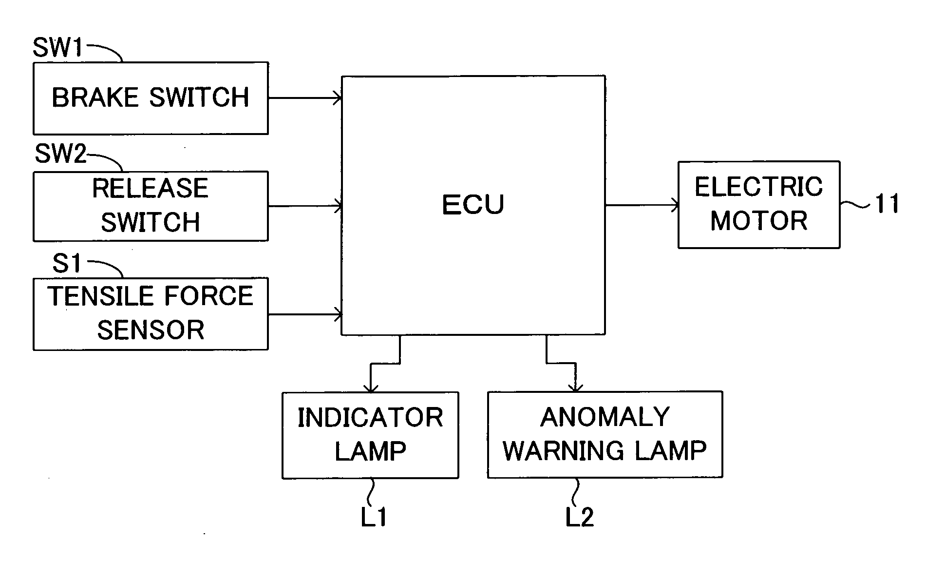
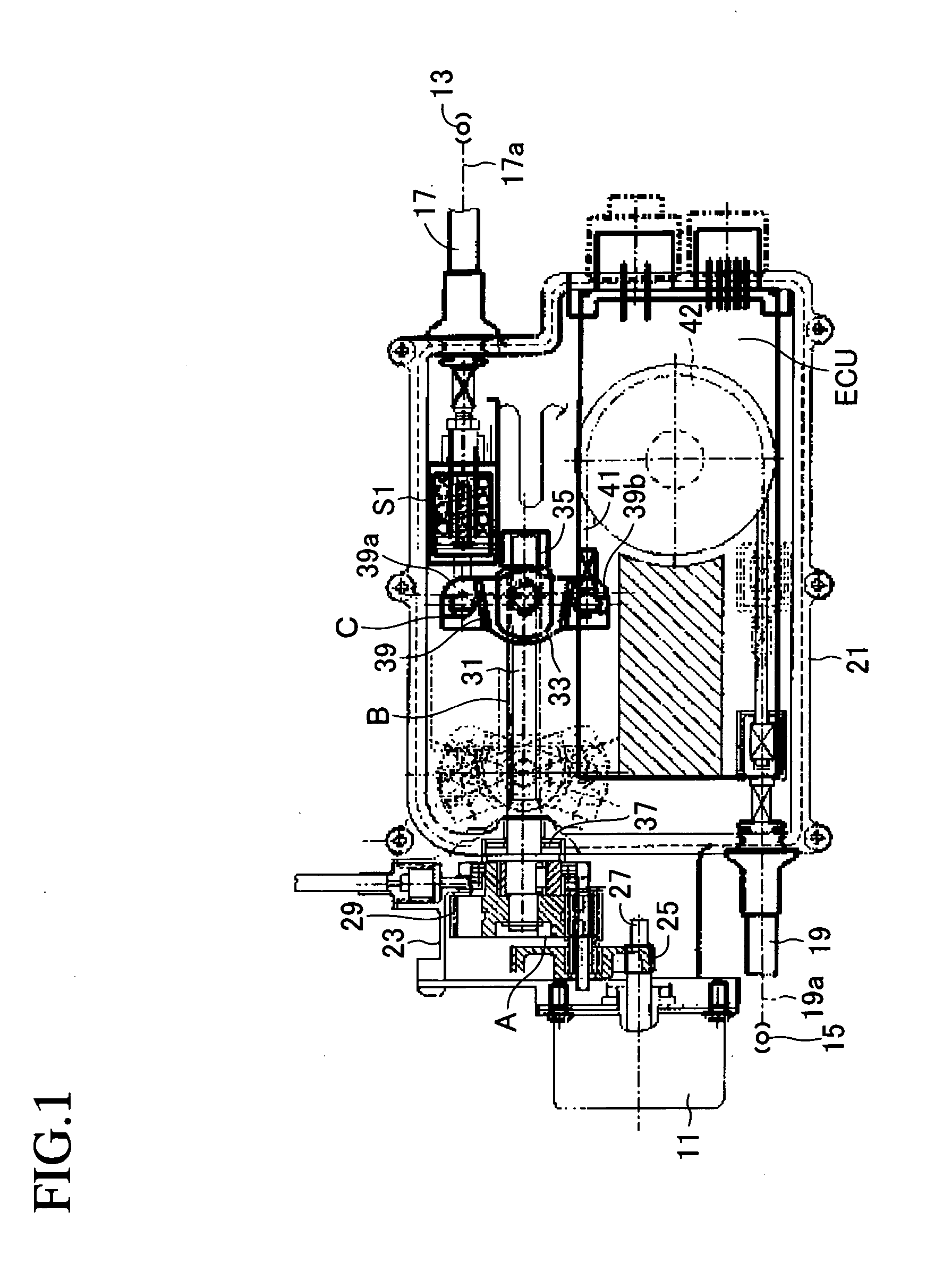
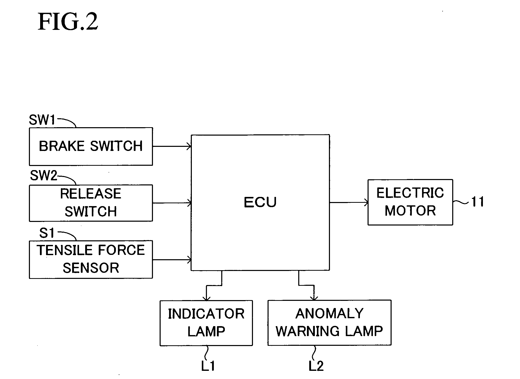
[0027] An embodiment of the present invention will be described with reference to the drawings. FIG. 1 shows an actuator of a motor-driven parking brake apparatus for a vehicle to which the present invention is applied. This actuator comprises a speed reduction mechanism A for transmitting rotational drive force, which is an output of an electric motor 11, while reducing the rotational speed; a conversion mechanism B for converting into a linear drive force the rotational drive force of the electric motor 11 which is transmitted through the speed reduction mechanism A; an equalizer mechanism C driven by the linear drive force output from the conversion mechanism B and distributing the linear drive force to two output portions; two cables 17 and 19 which are connected to the corresponding output portions of the equalizer mechanism C and transmit the linear drive force to corresponding parking brakes 13 and 15; and an electric control unit ECU for controlling the rotation of the elect...


PUM


Abstract

A force sensor includes a shaft to which a magnet is fixed, and a case which can reciprocate with respect to the shaft and to which a Hall IC element is fixed. The Hall IC element outputs an output voltage which changes in accordance with relative displacement between the Hall IC element and the magnet. A main spring is interposed between the shaft and the case and elastically deforms in accordance with force produced between the shaft and the case in the reciprocating direction. A sub spring is provided in order to impart a preload such that when the amount of elastic deformation of the main spring is substantially zero, no axial clearance is formed between a flange portion of the shaft and one end portion of the main spring, and no axial clearance is formed between the case and the other end of the main spring.

Description

BACKGROUND OF THE INVENTION [0001] 1. Field of the Invention [0002] The present invention relates to a force sensor and a motor-driven parking brake apparatus using the force sensor, and is applicable to, for example, a parking brake apparatus for a vehicle. [0003] 2. Description of the Related Art [0004] A conventional force sensor includes a first member to which a magnet is fixed; a second member to which an electrical element is fixed, wherein an output voltage of the electrical element varies with relative displacement in relation to the magnet; and a main spring which is interposed between the first member and the second member, and elastically deforms in accordance with force in the reciprocating direction produced between the first member and the second member. International patent application laid-open Nos. 02 / 20324 (WO 02 / 20324 A1) and 02 / 057122 (WO 02 / 057122 A1) disclose such a force sensor. [0005] Also, these publications disclose a motor-driven parking brake apparatus u...

Claims


Application Information

Patent Timeline
IPC IPC(8): F16D66/00F16D65/28
CPCB60T13/746G01L1/122G01L1/04F16D2125/582
Inventor TACHIIRI, YOSHIKAZUKISO, TAKAHIROSAITO, NOBUYUKI
Owner ADVICS CO LTD
Why Eureka
Try Eureka