Lithographic apparatus and a device manufacturing method

a technology of lithographic apparatus and manufacturing method, which is applied in the direction of photomechanical apparatus, instruments, optics, etc., can solve the problems of unwanted positional and rotational drift of the component, internal stress of the fastener, and the tendency of the known fastener to displace the apparatus component, etc., and achieves small features and high precision

Active Publication Date: 2006-01-05
ASML NETHERLANDS BV
View PDF4 Cites 8 Cited by
  • Summary
  • Abstract
  • Description
  • Claims
  • Application Information

AI Technical Summary

Benefits of technology

[0007] An aspect of the invention is to provide a lithographic apparatus and device manufacturing method, which can manufacture devices having small features with high precision.
[0008] An aspect of the invention is to provide a lithographic apparatus and device manufacturing method, wherein parts of the apparatus may be fastened and held in desired positions with high accuracy.
[0009] An aspect of the invention is to provide a lithographic apparatus and device manufacturing method, wherein drift of components, which are locked in desired positions, may be prevented.
[0011] In this way, the first and second apparatus part may be fastened or clamped to each other, using a relatively low tightening torque during the tightening of the fastener. Therefore, the chances of the apparatus parts shifting with respect to each other during the tightening of the fastener is relatively low. Also, during assembly, the fastener may provide a desired relatively high clamping force for locking at least the one apparatus part firmly to the other under the application of the relatively low torque. Furthermore, after assembly, the fastener may induce relatively low internal stresses in the apparatus parts, so that stress related damaging and / or deformation and / or drift of the apparatus parts is prevented. The present invention is particularly advantageous for locking relatively fragile apparatus components precisely in desired operating positions. Such components may be, for example, adjustable optical elements, for example, mirrors and / or lenses, leaf-springs, wire-springs, quartz components, for example, quartz plates, and / or other components.
[0012] The fastener, which includes a shaft having a first threaded section and a second threaded section of different pitch, can also be called a ‘differential screw thread’ fastener. It is noted that fasteners including differential screw thread as such are described in U.S. Pat. No. 4,959,938 and U.S. Pat. No. 5,217,339. However, these fasteners are used for roofing systems and are further arranged to apply high torques to roofing components. In U.S. Pat. No. 3,727,471, a differential screw mechanism is described for both coarse and fine adjustment of a movable mirror. The present invention is based on the innovative concept, that a shaft having a first threaded section and a second threaded section of a different pitch is particularly advantageous in locking lithographic apparatus part in desired positions, for avoiding any further movement or drift of the parts with respect to each other after assembly.
[0015] This may provide the above-mentioned advantages, particularly concerning the avoidance or reduction of drift of apparatus components, so that devices can be manufactured with high precision.

Problems solved by technology

However, the known fastener tends to displace the apparatus component during assembly, when the fastener is being driven to a locking position.
After assembly, the fastener may induce internal stresses in the component which is locked into position by the fastener.
Such stresses may result in unwanted positional and rotational drift of the component.
Such drift of apparatus components may hamper a desired operating accuracy of the apparatus, making it difficult, if not impossible, to manufacture devices with desired small features using a lithographic process.
This torque is induced into the apparatus component via the screwhead pivot face (and thread windings engaged of the fastener), causing deformations in weak sections of the apparatus component as well as internal material stress.
This is a second potential source of undesired positional and / or rotational drift of the apparatus component after assembly.

Method used


Image

  • Lithographic apparatus and a device manufacturing method
  • Lithographic apparatus and a device manufacturing method
  • Lithographic apparatus and a device manufacturing method

Examples


first embodiment

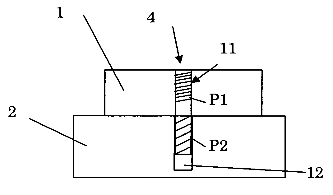
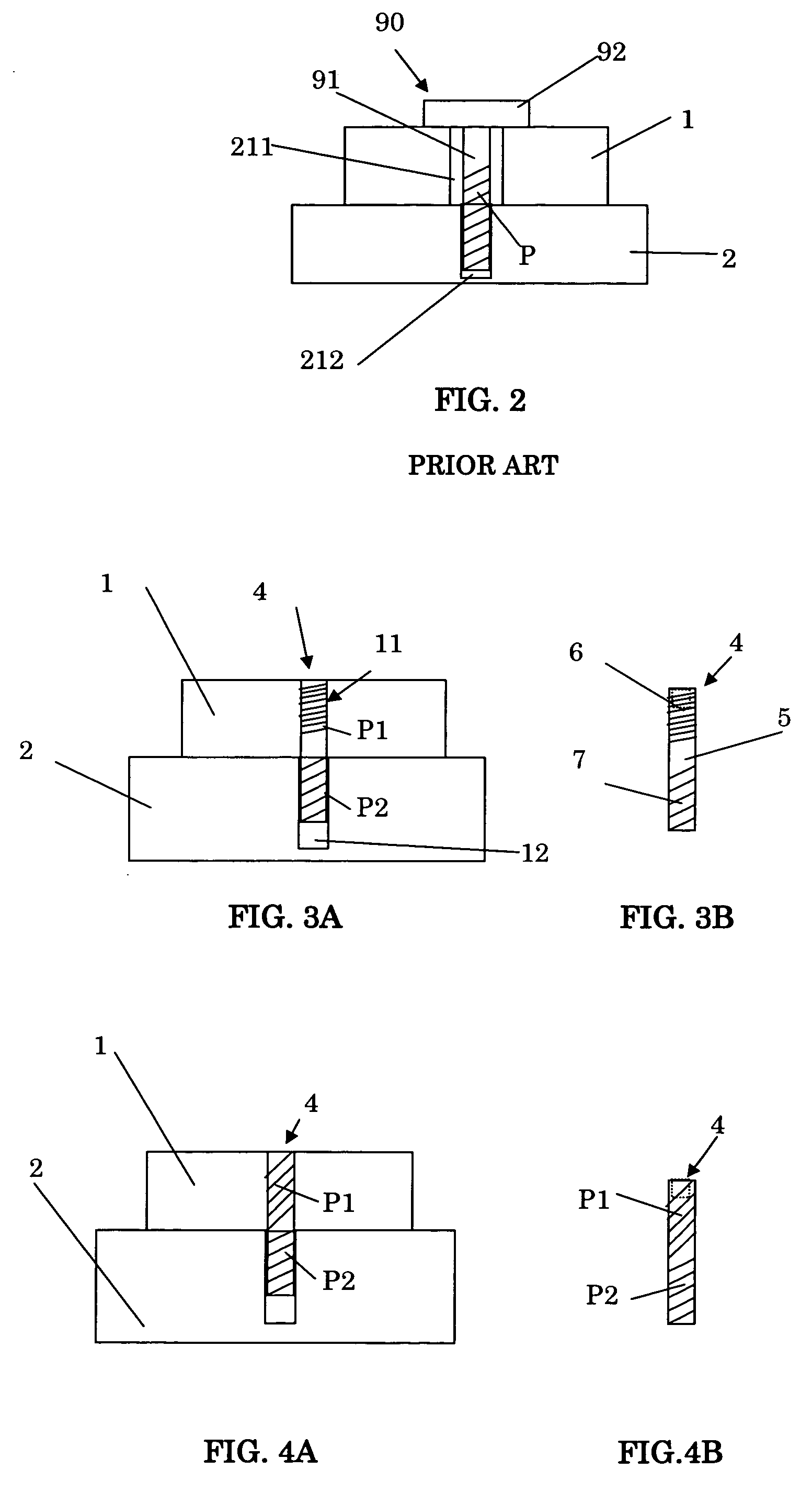
[0051]FIGS. 3A and 3B schematically show a first embodiment according to the present invention. In the first embodiment, the fastener 4 includes a cylindrical shaft 5 having a first threaded section 6 and a second threaded section 7. The pitch of the first threaded section 6 is depicted by reference sign P1, whereas the pitch of the second threaded section 7 is depicted by P2. In the present embodiment, the pitch P1 of the first section 6 is smaller than the pitch P2 of the second section 7. Preferably, at least one end of the fastener 5 is arranged to be engaged by an appropriate tool, such as a screw driver or the like, for driving the fastener 4 into and out of respective threaded openings that are discussed below. At least one end of the fastener may include, for example, a suitable control device, such as a slit or aperture having a suitable form. The present fastener 4, does not have a widened head part, such as the head of the prior art fastener as shown in FIG. 2.

[0052] In ...


PUM


Abstract

A lithographic apparatus and device manufacturing method are disclosed. The apparatus includes an illumination system for conditioning a beam of radiation, and a support structure for supporting a patterning device. The patterning device serves to impart the beam of radiation with a pattern in its cross-section. The apparatus also includes a substrate table for holding a substrate, a projection system for projecting the patterned beam onto a target portion of the substrate, and at least one fastener for fastening a first part of the apparatus to a second part of the apparatus. The fastener includes a shaft having a first threaded section and a second threaded section. The first threaded section and the second threaded section have different pitches.

Description

FIELD [0001] The present invention relates to a lithographic apparatus, a device manufacturing method, and a device manufactured thereby. BACKGROUND [0002] A lithographic apparatus is a machine that applies a desired pattern onto a target portion of a substrate. Lithographic apparatus can be used, for example, in the manufacture of integrated circuits (ICs). In that circumstance, a patterning device, such as a mask, may be used to generate a circuit pattern corresponding to an individual layer of the IC, and this pattern can be imaged onto a target portion (e.g. comprising part of, one or several dies) on a substrate (e.g. a silicon wafer) that has a layer of radiation-sensitive material (resist). In general, a single substrate will contain a network of adjacent target portions that are successively exposed. Known lithographic apparatus include so-called steppers, in which each target portion is irradiated by exposing an entire pattern onto the target portion in one go, and so-calle...

Claims


Application Information

Patent Timeline
Patent Type & Authority Applications(United States)
IPC IPC(8): G03B27/42
CPCG03F7/70833
Inventor DEKKER, MAARTEN CONSTANT BERNHARDKRIJNEN, EDWIN EDUARD NICOLAAS JOSEPHUS
Owner ASML NETHERLANDS BV
Why Eureka
Try Eureka