Light guide plate for surface light-emitting device and method of manufacturing the same

Inactive Publication Date: 2006-01-05
LG ELECTRONICS INC
View PDF2 Cites 102 Cited by
  • Summary
  • Abstract
  • Description
  • Claims
  • Application Information

AI Technical Summary

Benefits of technology

[0018] Another object of the present invention is to provide a method of manufacturing a light guide plate for a surface light-emitting device, wherein the V-cut grooves and optical waveguides are formed using a simple hot embossing process.
[0019] A further object of the

Problems solved by technology

Meanwhile, a mere 50% of light outputted from the fluorescent lamp is transmitted to the liquid crystal display panel while passing through the light guide plate, the diffusion plate and the prism sheet, which results from coupling and absorption losses in the light guide plate, loss in the reflection plate, absorption and surface reflection loss in the diffusion plate, an

Method used


Image

  • Light guide plate for surface light-emitting device and method of manufacturing the same
  • Light guide plate for surface light-emitting device and method of manufacturing the same
  • Light guide plate for surface light-emitting device and method of manufacturing the same

Examples


Embodiment Construction

[0037] Hereinafter, preferred embodiments of the present invention will be described in detail with reference to the accompanying drawings.

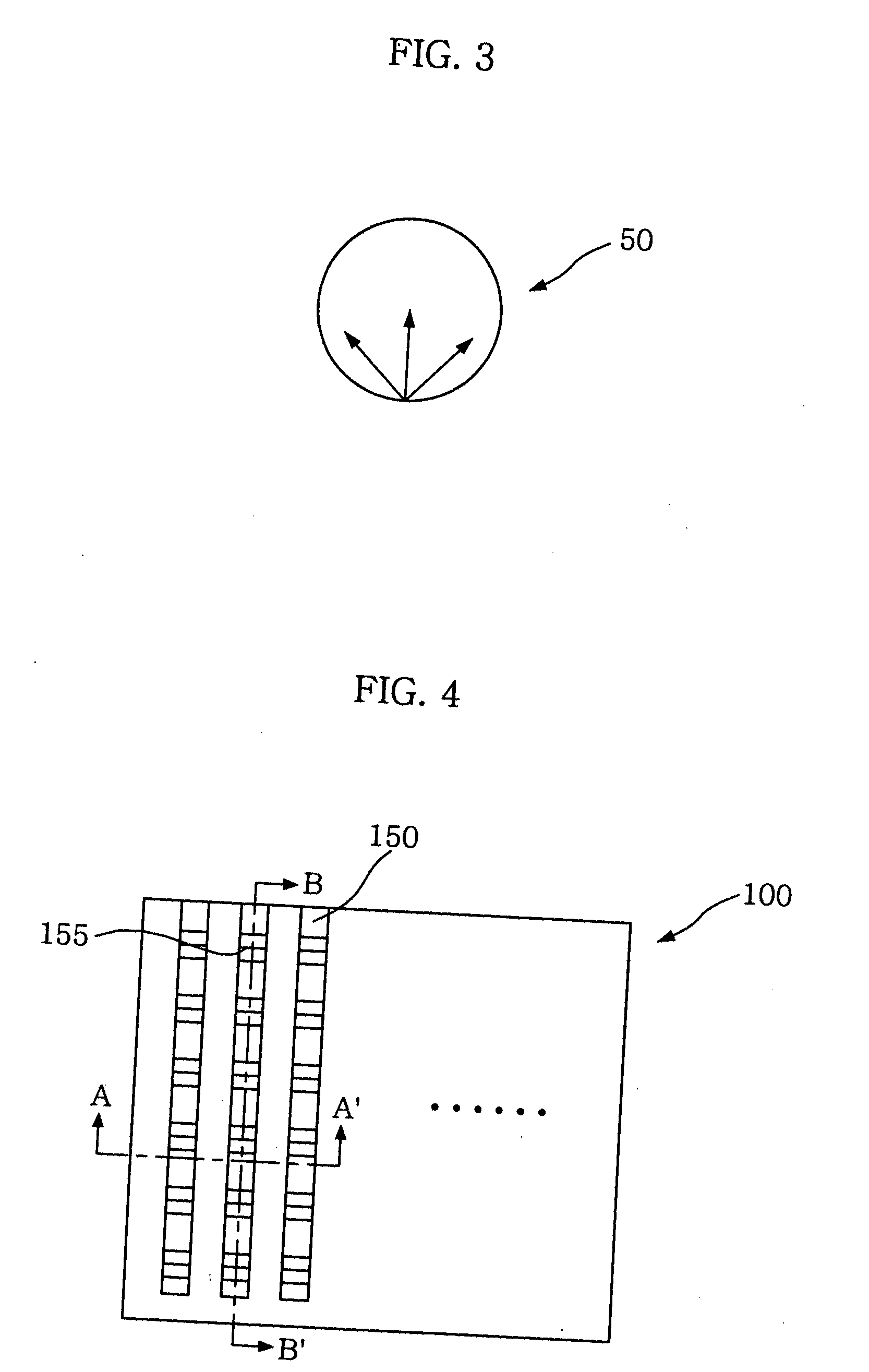
[0038]FIG. 4 is a schematic plan view of a light guide plate for a surface light-emitting device according to the present invention. Referring to FIG. 4, a light guide plate (100) includes a plurality of optical waveguides (150), which are covered by an upper cladding film and a lower cladding film, protrudes upwardly from the upper cladding film and are separated from each other. A plurality of V-cut grooves (155) are formed on each of the optical waveguides (150).

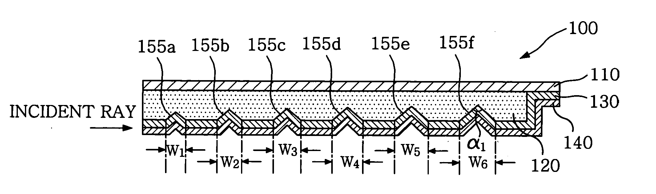
[0039]FIG. 5 is a sectional view of the light guide plate taken along line A-A′ in FIG. 4. When viewed from a cross-section taken along line A-A′ in FIG. 4, the light guide plate (100) includes an upper cladding film (100), a plurality of core films (120) separately formed on a lower surface of the upper cladding film (110) in the form of a stripe, a lower cladding film (130) so form...


PUM


Abstract

A light guide plate for a surface light-emitting device and a method of manufacturing the same are disclosed wherein the light guide plate is constructed in the form of an optical waveguide including an upper cladding film, core films formed with V-cut grooves, and a lower cladding film, so that since the upper and lower cladding films with a relatively low refractive index are respectively located on upper and lower surfaces of the core films, external foreign substances cannot penetrate into the core films, and the core films are not brought into contact with other components, whereby optical transmission properties are not changed and brightness can be also enhanced, and since the V-cut grooves are formed or both the V-cut grooves and optical waveguides are formed at the same time by means of a simple hot embossing process, the manufacturing costs can be saved.

Description

BACKGROUND OF THE INVENTION [0001] 1. Field of the Invention [0002] The present invention relates to a light guide plate for a surface light-emitting device and a method of manufacturing the same, and more particularly, to a light guide plate for a surface light-emitting device and a method of manufacturing the same, wherein the light guide plate is constructed in the form of an optical waveguide including an upper cladding film, core films formed with V-cut grooves, and a lower cladding film, so that, since the upper and lower cladding films with a relatively low refractive index are respectively located on upper and lower surfaces of the core films, external foreign substances cannot penetrate into the core films to prevent from being brought into contact with other components, whereby optical transmission properties are not changed to thereby enhance the brightness. [0003] 2. Description of the Related Art [0004] A liquid crystal display is basically constituted of a liquid cryst...

Claims


Application Information

Patent Timeline
IPC IPC(8): G02B6/10F21V7/04
CPCG02B6/0038G02B6/0065G02B6/005G02F1/1335
Inventor CHOI, CHUL CHAENOH, MIN SOOOH, HYUN HOPARK, CHAN HO
Owner LG ELECTRONICS INC
Why Eureka
Try Eureka