
Tooth whitening device

a tooth whitening and tooth technology, applied in the field of tooth whitening devices, can solve the problems of affecting the process of patients in the patient's favor, and achieve the effect of simplifying the tooth whitening process

Inactive Publication Date: 2006-01-05
PROFESSIONAL DENTAL TECH
View PDF8 Cites 72 Cited by
  • Summary
  • Abstract
  • Description
  • Claims
  • Application Information

AI Technical Summary

Benefits of technology

[0006] It is an object of the present invention to simplify the tooth whitening process.
[0007] It is a further object to provide a tooth whitening process which is easier for the patient to tolerate over the extended periods required for light activated bleaching.
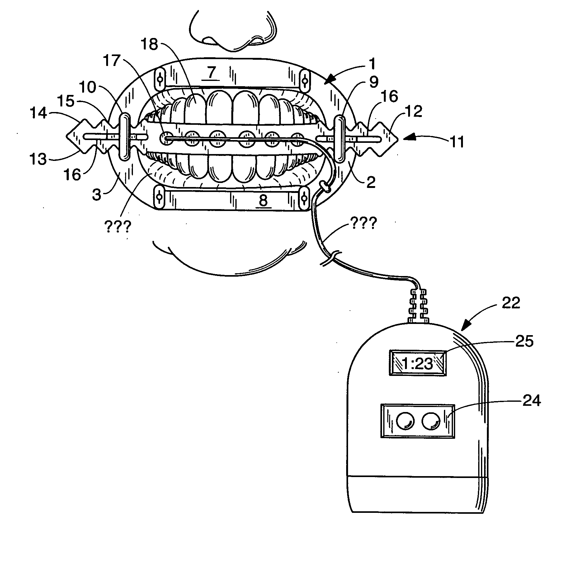
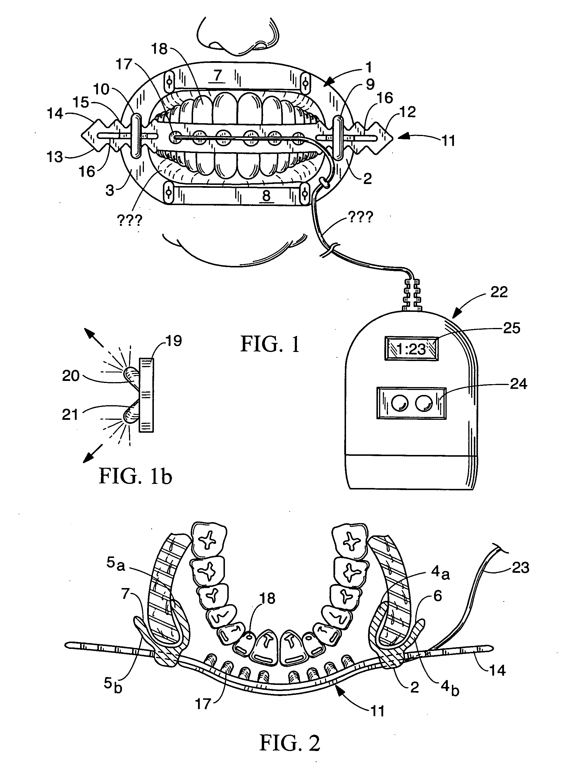
[0010] Using an array with multiple, small light sources such as LED's, the focal length can be kept very short, preventing dangerous and uncomfortable stray light from reaching the patient's eyes, and allows focusing the energy in an arch shape quite easily, as compared to the prior single, high-powered light, which required a parabolic type reflector to properly focus the light around the arch. Having the light sources on the retractor, mounted to the mouth, or integral with a mouth guard mounted within the mouth also reduces the amount of lip and cheek extension, further increasing comfort for the user.
[0011] Preferably, the light source used would be substantially out of the patient's line of sight, lessening patient anxiety, as opposed to the typical large and imposing light source and support structure that normally fills the patient's view.
[0013] To reduce cost of a home product, one light source could be used instead of an array, which is preferred for dental office use. The single light source could additionally be movable on an arched track with multiple indentions to act as stops, so that the light source could be manually moved from one position to the next, in response to a timer or upon receiving an audio or visual signal from a controller or from the power source, to facilitate proper treating of each area of the full arch. This also reduces the size of the device, increasing user comfort.

Problems solved by technology

Of course, having to sit immobile for extended periods during bleaching can be very uncomfortable for the patient, and can ultimately detrimentally affect the process if the patient moves.

Method used


Image

  • Tooth whitening device
  • Tooth whitening device
  • Tooth whitening device

Examples


Embodiment Construction

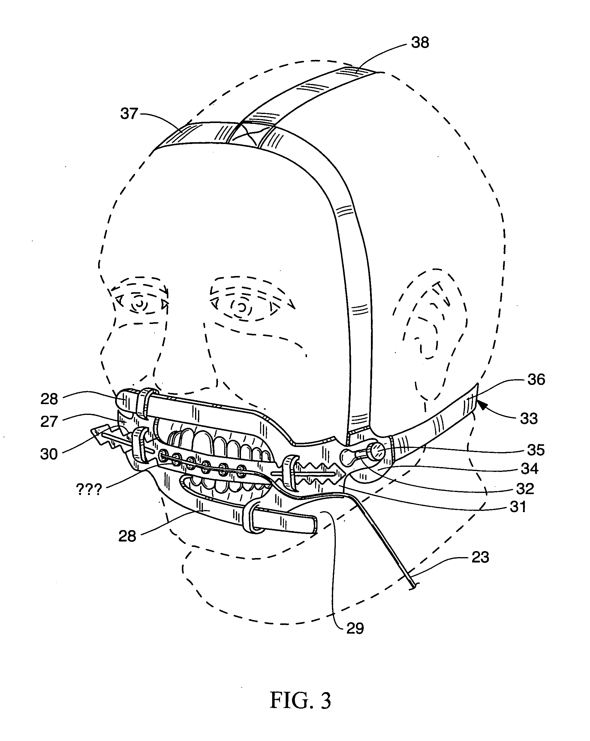
[0022] The present invention will be described relative to FIG. 1. A cheek or jaw retractor 1 has a pair of opposed curved arch portions 2 and 3. Each arch portion is composed of a pair of inner and outer walls, 4a, 4b and 5a, 5b, defining a lip receiving channel 6, 7, therebetween. These opposed arch portions are fitted to the mouth and lips which are spread apart to hold the mouth open, so that the cheek and lips remain retracted during the tooth whitening process. Lip protectors 7 and 8, having similar lip receiving channels, can be fitted over the upper and lower lip portions not received within the arched portions, to provide full lip protection, by shielding the lips from the whitening composition. These can be engaged in a snap fit with the opposed arch portions. All of these components may be made from any suitable resilient plastic material.

[0023] Each arched portion 2, 3 has a C-shaped support channel 9, 10 mounted on an outer surface of the outer wall thereof. These are ...


PUM


Abstract

The invention is a locally mounted light source for light activation of tooth whitening compositions. A support in the form of a bridge attached to a retractor or as part of a mouth guard has integral therewith, a small and lightweight light source, such as could be provided by one or more high-intensity LED's, though other light sources could be used. The light source may be in the form of an array, powered by either a direct electrical connection to a power supply or by battery power, for example, with a battery pack worn by the user. The light source is thus located in proximity to the tooth surfaces regardless of head movement or orientation, increasing user mobility and comfort.

Description

CROSS REFERENCE TO RELATED APPLICATION [0001] This application claims priority in U.S. Provisional application no. 60 / 583,999 filed Jun. 30, 2004.BACKGROUND [0002] Tooth whitening in the dental office historically has been performed by using a hydrogen-peroxide gel applied to the teeth, which bleaches the tooth surfaces when activated by light. The light source is typically a large, floor or chair based light source. [0003] There are several different gel products on the market, which are formulated so as to react to a specific wavelength and type of curing light being used, to activate the bleaching process. In most cases, the activation energy of the curing light is UV, heat, or laser. A recent addition to the list of light sources is a high intensity LED (Light Emitting Diode), which primarily emits blue light. [0004] During an in-office dental whitening procedure, a patient is fitted with a dental retractor, which pulls back the lip tissue, to expose the upper and lower teeth to...

Claims


Application Information

Patent Timeline
Patent Type & Authority Applications(United States)
IPC IPC(8): A61C3/00A61C5/00
CPCA61C1/088A61C19/066A61C5/14A61C5/90
Inventor SALE, DAVID WILLIAMHAYNES, RONALD W.
Owner PROFESSIONAL DENTAL TECH
Learn More