Communication apparatus and method for reconfiguring communication apparatus

Inactive Publication Date: 2006-01-05
PANASONIC INTELLECTUAL PROPERTY CORP OF AMERICA
View PDF20 Cites 22 Cited by
  • Summary
  • Abstract
  • Description
  • Claims
  • Application Information

AI Technical Summary

Benefits of technology

[0011] It is an object of the present invention to provide a communication apparatus and communication apparatus reconfiguration method for reducing the time required for download without decreasing the user capacity of the entire system, and as a result, switching between communication systems for a short time.
[0012] The object is achieved by only reconfiguring a portion differen

Problems solved by technology

From these viewpoints, in the constitution as disclosed in Patent Document 1, a call is suspended or disconnected during download, and it is not possible to perform fast handover between radio communication systems.
Further, as disclosed in Patent Document 2, when a download dedicated channel is provided to download programming data, there are possibilities that spectral efficiency deteriorates and the user capacity of the entire system decreases.
When data of a radio communication system with a large amount (hereinafter, referred to as “large-scale”) of programming data is downloaded during communication in a narrowband radio communication system with low transmission rates, retransmission is apt to occur and it takes enormous time to complete the download.
In particular, retransmission occurs remarkably in poor radio signal propagation circumstances.
Further, when individual mobile communication terminals are operated to perform fast

Method used


Image

  • Communication apparatus and method for reconfiguring communication apparatus
  • Communication apparatus and method for reconfiguring communication apparatus
  • Communication apparatus and method for reconfiguring communication apparatus

Examples


Example

Embodiment 1

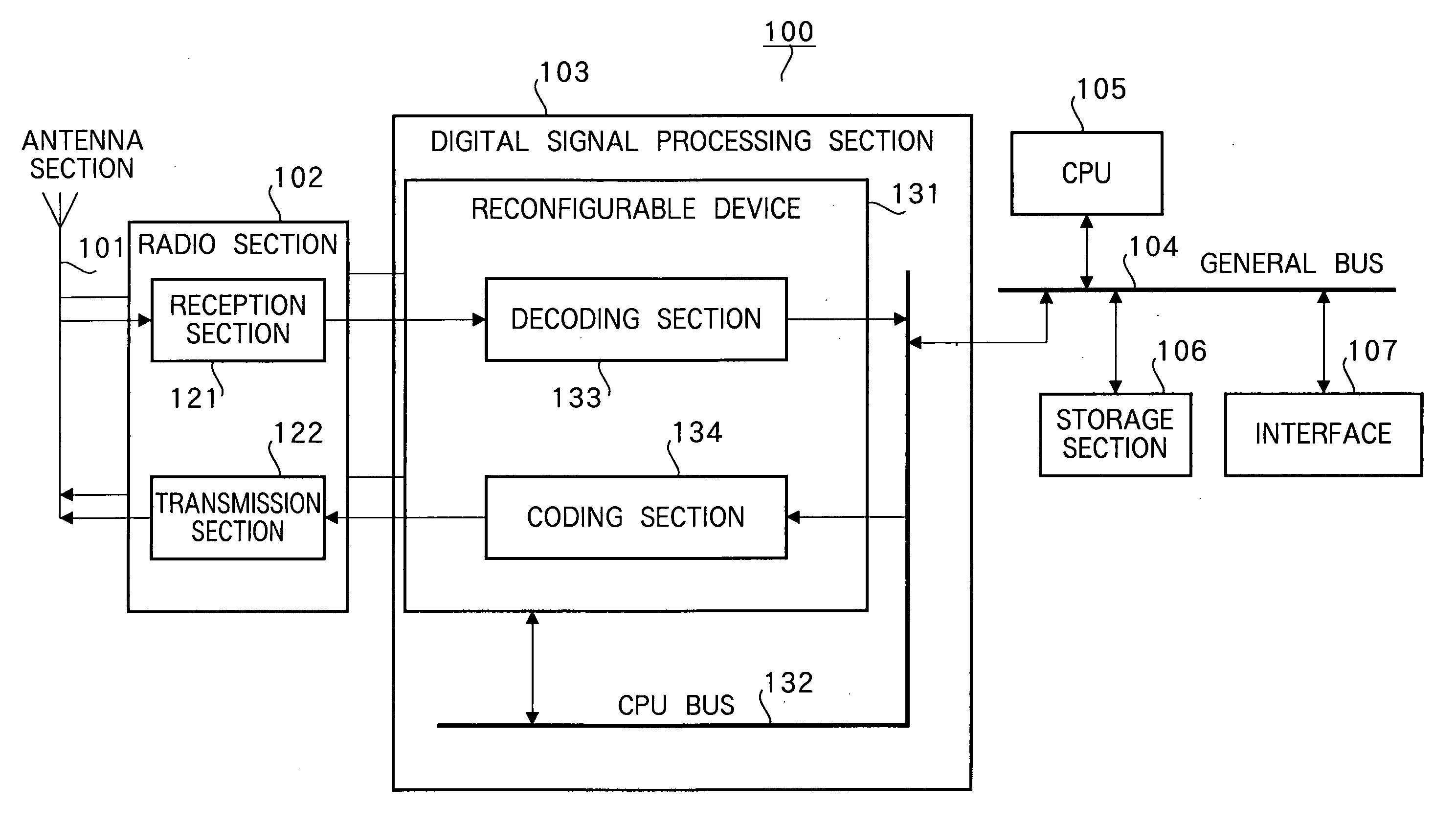
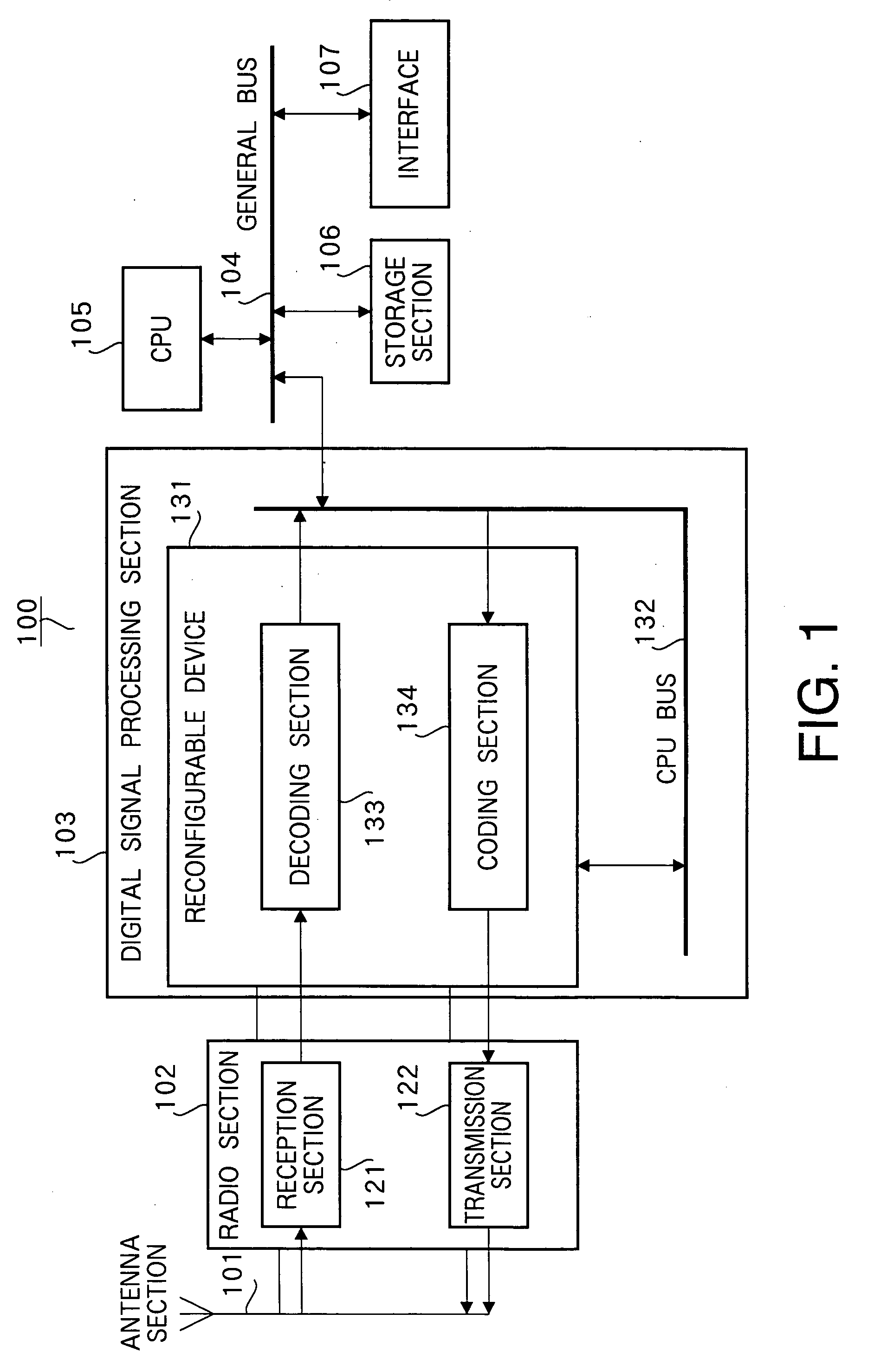
[0043]FIG. 1 is a block diagram illustrating a configuration of a communication apparatus according to Embodiment 1 of the present invention. Communication apparatus 100 is mainly comprised of antenna section 101, radio section 102, digital signal processing section 103, general bus 104, CPU 105, storage section 106 and interface 107. Radio section 102 is mainly comprised of reception section 121 and transmission section 122. Digital signal processing section 103 has reconfigurable device 131, and reconfigurable device 131 is connected to general bus 104 via CPU bus 132.

[0044] In FIG. 1, radio section 102 has reception section 121 and transmission section 122, and performs predetermined radio processing on a reception signal and transmission signal.

[0045] Reception section 121 receives a signal transmitted from a communicating party station not shown via antenna section 101, performs predetermined radio reception processing (downconverting, A / D conversion, etc.) on th...

Example

Embodiment 2

[0147]FIG. 18 is a block diagram illustrating a configuration of a communication apparatus according to Embodiment 2 of the present invention. Communication apparatus 300 in FIG. 18 has signal processing card section 301 detachable to the outside, thereby enables a reconfigurable digital signal processing portion to be detachable, and in this respect, is different from the communication apparatus in FIG. 1.

[0148] Signal processing card section 301 is mainly comprised of digital signal processing section 103, radio-section communication section 302, CPU communication section 303, and identification information section 304, and further provided with display 108 connected to general bus 104.

[0149] Digital signal processing section 103 transmits / receives an input / output signal to / from radio section 102 via radio-section communication section 302. Further, the section 103 transmits / receives an input / output signal to / from CPU 105 via CPU communication section 303. Identific...

Example

Embodiment 3

[0160]FIG. 22 is a block diagram illustrating a configuration of a communication apparatus according to Embodiment 3 of the present invention. Communication apparatus 400 in FIG. 22 has attaching / detaching detection section 401, display section 402, power source supply section 403, and battery 619, enables a portion that reconfigures only a portion different among a plurality of radio communication systems to be detachable, halts power supply to a radio transmission portion when the portion to reconfigure is detached, while supplying power to the radio transmission portion and the portion to reconfigure when the portion to reconfigure is attached, and in this respect, differs from the communication apparatus in FIG. 18.

[0161] Attaching / detaching detection section 401 detects connection between signal processing card 301 and communication apparatus 400, and when the card 301 is not connected, inputs a detaching detection signal to CPU 105 to notify that signal processin...


PUM


Abstract

Digital signal processing section 103 has reconfigurable device 131, and reconfigurable device 131 configures decoding section 133 and coding section 134 by programming data. Decoding section 133 acquires synchronization from a signal output from reception section 121, and demodulates and decodes the signal. CPU 105 downloads programming data of another radio communication system to store in storage section 106 via general bus 104. Further, CPU 105 reads out the stored programming data, and reconfigures reconfigurable device 131. Storage section 106 stores the programming data.

Description

TECHNICAL FIELD [0001] The present invention relates to a communication apparatus and communication apparatus reconfiguration method, and more particularly, to a communication apparatus and communication apparatus reconfiguration method suitable for use in a hand over system for switching between a plurality of radio communication systems. BACKGROUND ART [0002] Currently, various radio communication systems exist such as 2nd generation radio communication systems such as PDC and GSM, 3rd generation radio communication systems such as W-CDMA, and PHS and wireless LAN. As a technique for supporting a plurality of radio communication systems using a single radio apparatus, software defined radio exists that varies between functions by updating of software (programming data). [0003] When switching between radio communication systems (which generally means handover between radio communication systems or the case of updating programming data, but it is herein assumed that handover include...

Claims


Application Information

Patent Timeline
IPC IPC(8): H04M1/00H04B1/40H04L12/28H04W8/24
CPCH04B1/0003H04B1/0028H04W8/245H04B1/3816H04B1/406H04B1/005H04W56/00
Inventor YAMANAKA, RYUTAROISHIKAWA, TOSHIHIRO
Owner PANASONIC INTELLECTUAL PROPERTY CORP OF AMERICA
Why Eureka
Try Eureka