
Method and apparatus for cleaning fluids

a technology of cleaning fluids and methods, applied in the direction of cleaning processes and equipment, electrostatic cleaning, centrifuges, etc., can solve the problems of oil oil can also be contaminated by other substances or materials, and lose lubrication integrity

Active Publication Date: 2006-01-05
LUBEMASTER AUSTRALIA
View PDF11 Cites 23 Cited by
  • Summary
  • Abstract
  • Description
  • Claims
  • Application Information

AI Technical Summary

Benefits of technology

[0010] The present invention aims to provide a method and apparatus for fluid cleaning, which may at least partially overcome the abovementioned disadvantages or provide the consumer with a useful or commercial choice. The present invention in a further aspect aims to provide an improved centrifugal cleaner for liquids and liquid cleaning apparatus which incorporates a centrifugal cleaner. The present invention in yet a further aspect aims to provide an improved vacuum dehydration unit and a liquid cleaning apparatus which incorporates a vacuum dehydration unit.
[0018] Means such as connecting pipes suitably connect the first pump to the heating unit and the heating unit to the centrifugal cleaner. The purpose of the heating unit is to heat the oil, creating a reduction in the viscosity of the oil thereby allowing the apparatus to be used to clean heavier grade oils. The heating unit may preferably be mounted after the first pump discharge to receive oil from the pump and allow the oil to pass through prior to entry to the centrifugal cleaner. The heating element of the heating unit may be a thermostatically controlled element and may also allow the operator to pre-set a temperature for optimum operation.
[0023] The impeller may be provided with a loose inner sleeve to prevent tip leakage. The inner sleeve may be free to rotate under the frictional drag of the vanes and the viscosity of the oil. The impeller may preferably move the oil away from the base at a rate which is quicker than the flow from the nozzles. This may prevent or reduce the build-up of oil in the base which could cause the rotor to slow or lose efficiency.

Problems solved by technology

Lubricating oils can often be contaminated by water or moisture.
Oil can also be contaminated by other substances or materials such as microscopic wear debris or contaminated by other liquids.
Contamination of oil results in loss of lubrication integrity and can result in excessive wear of machinery and plant.
Notwithstanding the simplicity and efficiency with which such devices separate solids from the fluid passing therethrough, there are a number of limitations attached to their usage which have hither-to served to limit their widespread use.
These arrangements have not been particularly effective in removal of the fluid from the base of the rotor.
A failure to accomplish this effectively leads to the fluid “backing up” or accumulating in the base and this affects the rotor speed and therefore separation efficiency.
All these devices have significant limitations in either their water removal capabilities, ease of operation, capital costs, or operating costs.
Some of these devices are ineffective in separating oil-water emulsions and are not capable of removing dissolved water.
Centrifuges are effective in removing free water from the oil but are expensive and have limited capability in separating oil-water emulsions.
In addition, water-absorbing filters have a limited capacity for water and are typically only used in applications where trace amounts of water are present.
While vacuum distillation and mass transfer systems do remove free, emulsified and dissolved water, they have several drawbacks that have prevented their widespread use.
Vacuum purifiers are also subject to foaming within the vessels as water is vaporized within the oil.
This foam has a lower specific gravity than the oil can cause malfunctioning controls and a reduction in the performance of the purifier.
The drawbacks associated with vacuum oil purifiers have prohibited these purifiers from being widely used and / or the purifiers are not practical on the majority of lubrication or hydraulic systems.
Because of their relatively large size and costs, they are limited to non-mobile, stationary applications, and are not practical for use on mobile equipment.
Further due to their high capital cost, they are typically not permanently installed in a system unless it is a relatively large, expensive lubrication or hydraulic system.
When the purifier is being used in this manner, the oil in the machines that are not connected to the purifier can become contaminated with water.
This oil will remain contaminated until the purifier can be reattached to them and the oil dehydrated again.
It must, however, be recognized that the presence of either pores or defects in a membrane used for this purpose will result in the hydraulic permeation of the oil to the permeate side.
This situation will result in the loss of oil.
It will also allow the non-volatile oil to coat the permeate side of the membrane, thereby fouling the membrane and reducing its effectiveness in permeating water.

Method used


Image

  • Method and apparatus for cleaning fluids
  • Method and apparatus for cleaning fluids
  • Method and apparatus for cleaning fluids

Examples


Embodiment Construction

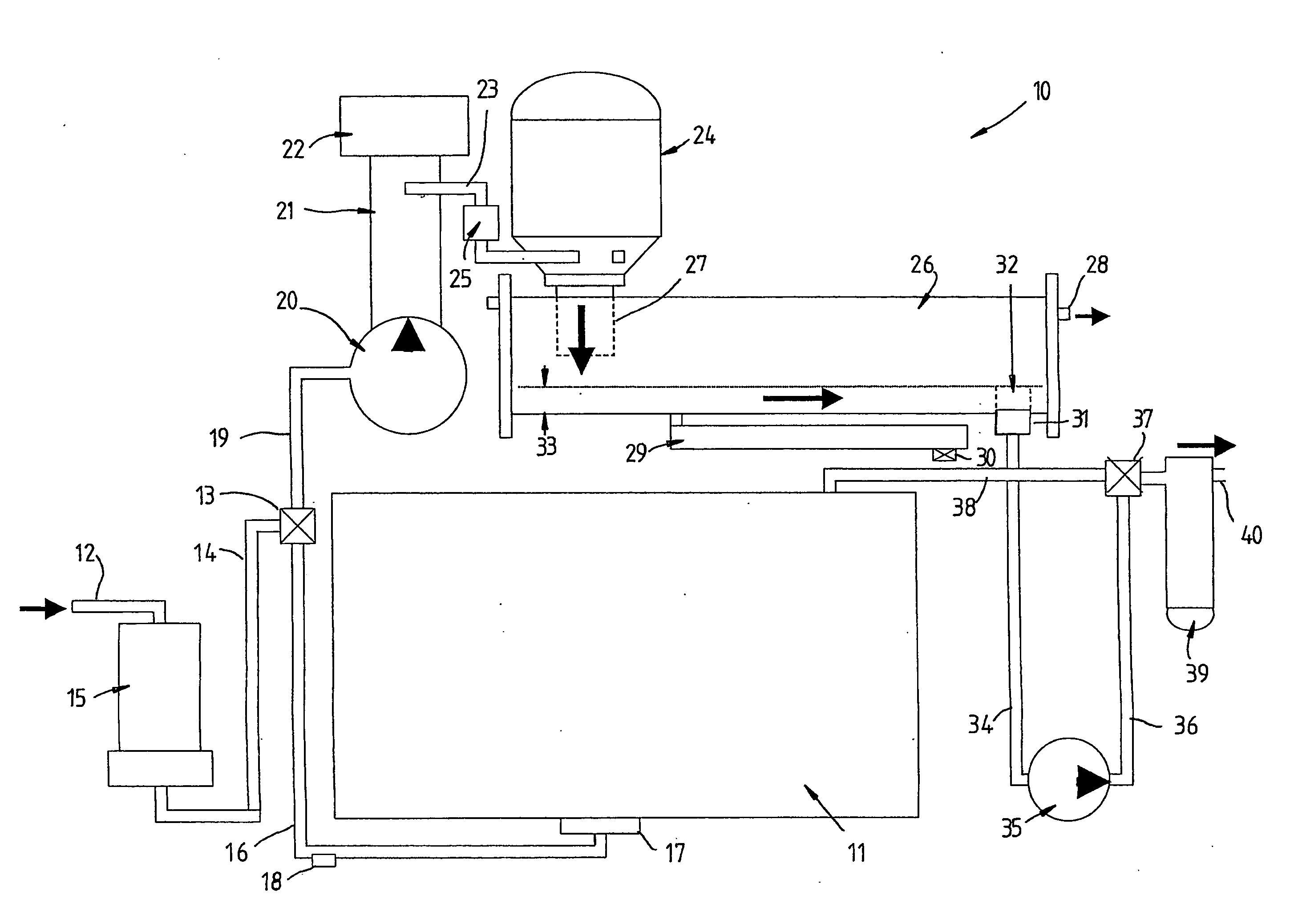
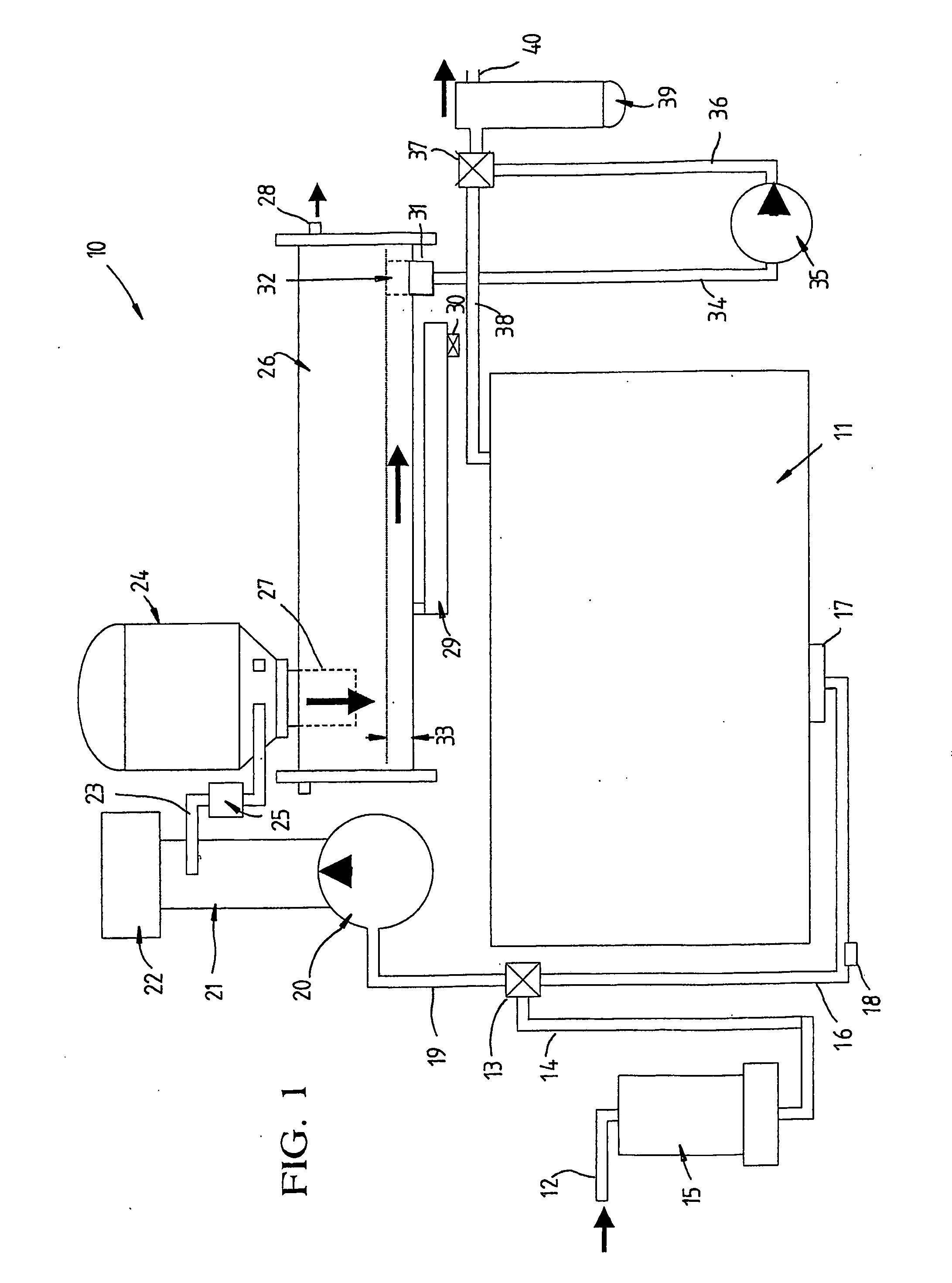
[0043] Referring to the drawings and firstly to FIG. 1, there is illustrated schematically oil cleaning apparatus 10 according to an embodiment of the invention, the apparatus being adapted to clean either oil held within a holding tank 11 or oil supplied from an inlet pipe 12 which may be connected to an external source. A three way selector valve 13 is connected to the inlet 12 though a pipe line 14 via a suction strainer 15 which will remove larger particles and contaminants down to 25 μm size. The three way selector valve 13 is also connected to the holding tank 11 via piping 16 to a suction sump 17 located in a lower portion of the holding tank 11. The piping 16 includes a drain plug 18 which allows drainage of oil from the tank 11.

[0044] The outlet side of the valve 13 is connected by pipeline 19 to the inlet of a first pump 20 directly coupled to, to be driven by, an electric drive motor. The outlet of the pump 20 is coupled to an in-line heater 21 which has a thermostat and...


PUM

PropertyMeasurementUnit
sizeaaaaaaaaaa
pressureaaaaaaaaaa
pressureaaaaaaaaaa

Abstract

Apparatus (10) for cleaning fluids such as oils comprising an inlet (12) for fluid to be cleaned, a heating unit (21) for heating the fluid, a centrifugal cleaner (24), a vacuum dehydration unit (26), a holding tank (11) and a fluid outlet (40). A first valve (13) controls communication between a first pump (20) and the inlet (12) or holding tank (11) to pump fluid from the inlet (12) or holding tank (11) to the heating unit (21) for conveyance to the centrifugal cleaner (24), the outlet of which is connected to the vacuum dehydration unit (26) and a second valve (37) controls communication between a second pump (35) and tank (11) and outlet (40) to either enable fluid to be recirculated back to the tank (11) or supplied to the outlet (40).

Description

TECHNICAL FIELD [0001] The present invention relates to purification of fluids and in particular to a method and apparatus for cleaning oils or other liquids. BACKGROUND ART [0002] In operation of machinery and other plant it is important to ensure the cleanliness and integrity of lubricating oils used. Lubricating oils can often be contaminated by water or moisture. Oil can also be contaminated by other substances or materials such as microscopic wear debris or contaminated by other liquids. Contamination of oil results in loss of lubrication integrity and can result in excessive wear of machinery and plant. [0003] Different types of equipment are known for use in separation of solids from liquids. Centrifuges are a common form of device which can be used for this purpose and are of two general types, namely sedimentation centrifuges, which require a difference between the densities of the two or more phases to be separated; and centrifugal filters, in which the solid phase is supp...

Claims


Application Information

Patent Timeline
Patent Type & Authority Applications(United States)
IPC IPC(8): B08B3/00B01D17/00B01D17/038B04B5/00B04B9/06C10G53/02C10M175/00
CPCB01D17/005B04B5/005B04B9/06C10G53/02C10M175/0058C10M175/0091B01D17/0217B01D17/044B01D17/10Y10S494/901
Inventor SMITH, ROBERT CARRINGTON
Owner LUBEMASTER AUSTRALIA
Learn More