Horticultural lighting system

Inactive Publication Date: 2006-01-12
ROSEMAN DOUGLAS LEE +1
View PDF8 Cites 55 Cited by
  • Summary
  • Abstract
  • Description
  • Claims
  • Application Information

AI Technical Summary

Benefits of technology

[0034] It is therefore a general objective of this invention to provide a versatile and adaptable lighting system utilizing high efficiency luminary elements mounted on a substrate providing heat and physical stress management. A universal impedance-matching power supply, time-variable and color-intensity-variable spectral adjustments and electrical connection means are used.
[0035] A further objective is durability and high lumen maintenance, which are native features of LEDs and are far superior to any of the glass-based luminary elements currently available.

Problems solved by technology

Current fluorescent and gas discharge lights operate at relatively low conversion efficiency usually below twenty percent, emit excess light spectra, and lack longevity leaving room for improvement.
Until the advent of high-output third generation LEDs, LED plant-growth systems were unusable and unaffordable for anything more than tiny seedlings, and were not practical due to the large number of second gen.
Daily on-off cycling typical in growing applications causes undue stress and premature failure of the gas-discharge lights.
Never before has it been possible to achieve the longevity of a lighting fixture as with LEDs.
Firstly, utilizing a combination of chemical elements as the phosphor (light-emitting substance), some fluorescent bulbs are designed to produce horticulturally-specific output, i.e. red and blue, but the phosphors used result in a great proportion of spectra of which the plant utilizes only a small amount resulting in marginal performance.
Secondly, these bulbs also typically utilize a heated filament, which is under stress and is frequently a cause of failure.
Thirdly, fluorescent bulbs utilize mercury as the exciter element, which is toxic and escapes when the bulb eventually breaks.
High Intensity Discharge (HID) varieties operate under plasmatic conditions and are therefore inherently short-lived.
These bulbs emit relatively intense infrared radiation and are known to cause damage to plant and animal tissue if precautions are not taken.
Examples of HID lighting technologies include the following: High Pressure Sodium (HPS): The spectra emitted from this type of light contain a proportion of some of the red light required for plant growth, but lack especially in the blue spectra resulting in abnormally slow-growing plants.
In the event that the outer glass envelope breaks, HPS lamps emit hazardous levels of ultraviolet (UV) light.
Halide and Mercury Vapor: These bulbs partially solve the problem of lack of blue light, but also emit high proportions of green and yellow light resulting in a very white-appearing light, much of which is wasted as it is only utilized in small amounts by the plant.
While this is a sound concept, precise spectrum matching and longevity are limited.
LEDs assembled on circuit boards and small growth chamber which is limited for tiny seedlings.
LEDs are very sensitive to excessive current.
Typical commercially-available LED lamps utilize resistors as the current-limiting devices, which are non-regulating resulting in inconsistent light output and premature failure, and are inherently wasteful resulting in excessive heat dissipation and power consumption.
High efficiency and longevity are generally sacrificed due to the high cost of impedance-matching supplies vs. the cost of a second gen.
LEDs is materially inefficient due to the light-output capability in comparison to the total mass of the device.
Other systems, as described in a NASA bulletin entitled “Plant Lighting Systems” are elaborate devices indicated for highly experimental use for culturing young seedlings in orbit, and are unavailable to the public.
These lighting systems still encounter limited light volume capability, which prohibits growing anything bigger than tiny young plants.

Method used


Image

  • Horticultural lighting system
  • Horticultural lighting system
  • Horticultural lighting system

Examples


Embodiment Construction

[0060] As will become evident by further study of the drawings, the present invention relates to a versatile lighting system especially for plant-growth illumination.

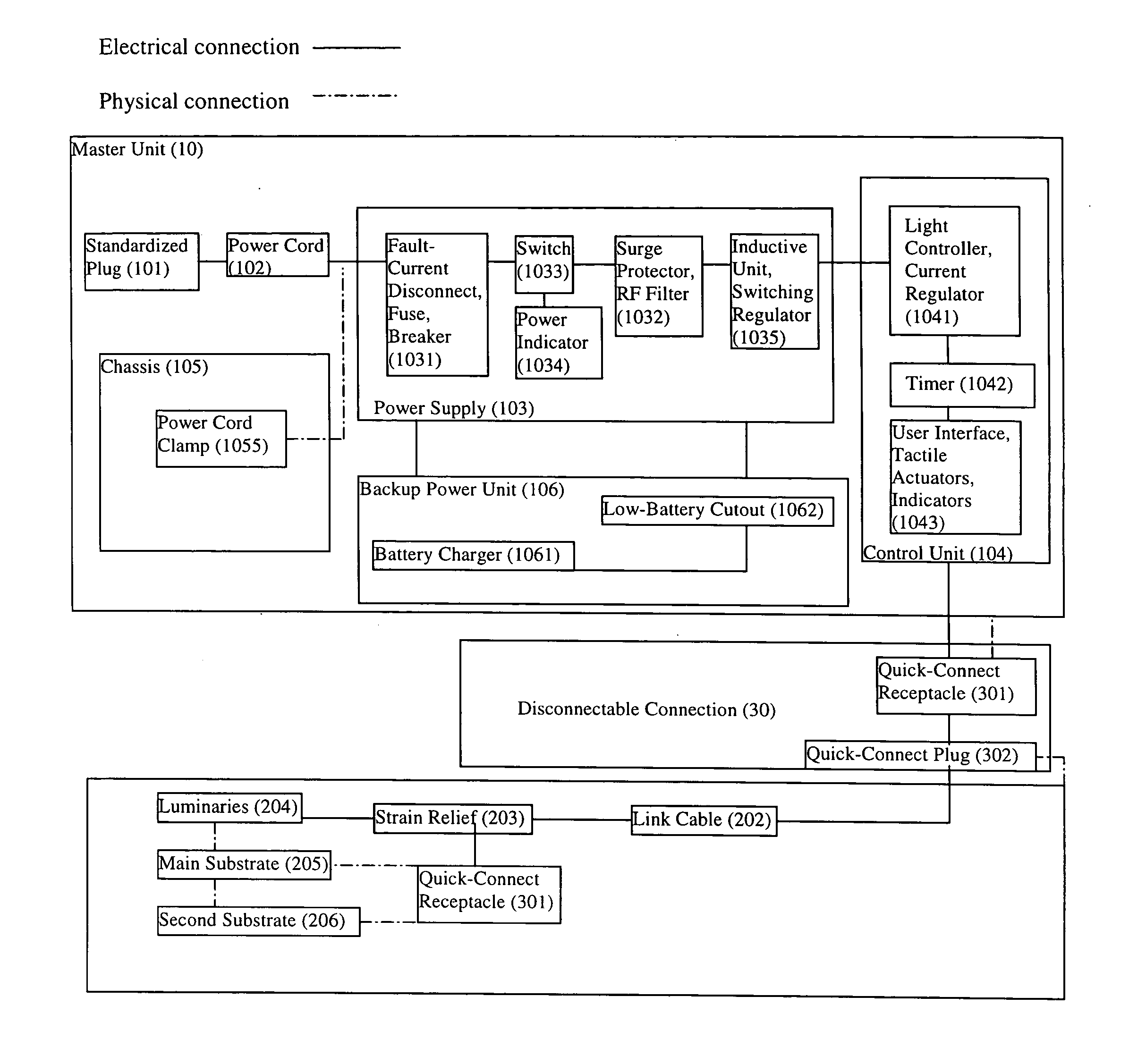
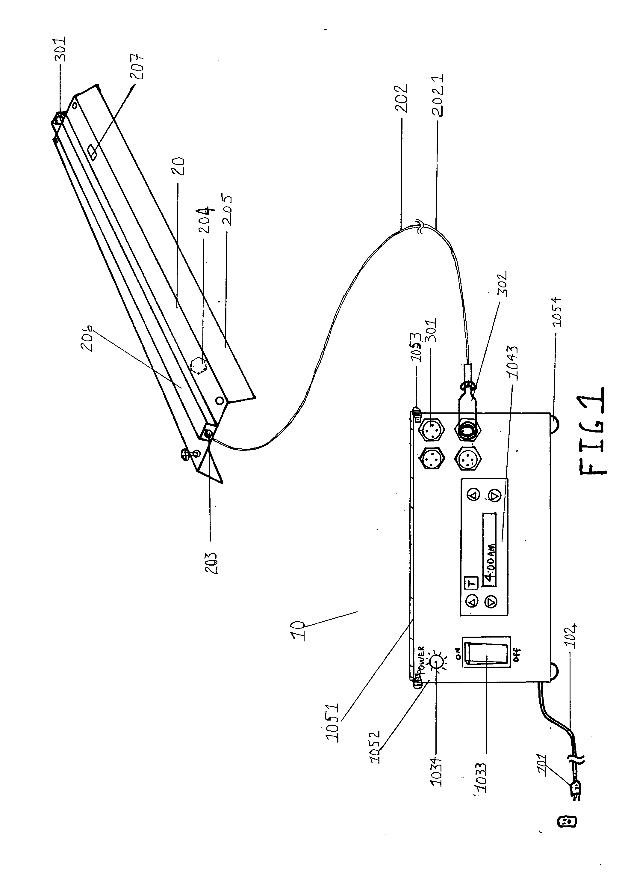
[0061] According to the preferred embodiment of the present invention, FIG. 1 of the drawings shows the horticultural lighting system comprising a master unit 10 and fixture 20. The master unit 10 includes a standardized plug 101 affixed to the end of a power cord 102 and attached to a chassis 105.

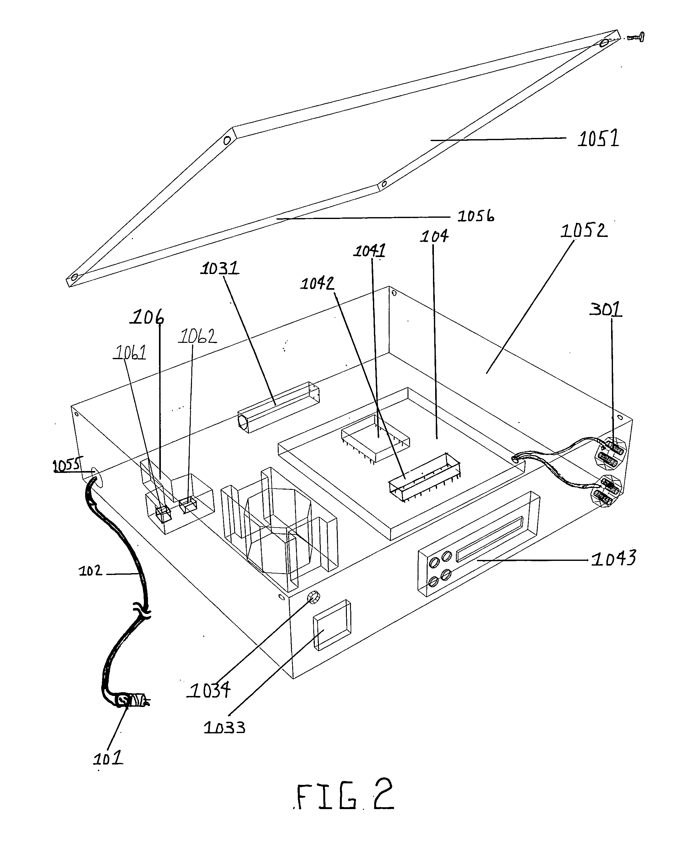
[0062] The chassis 105 comprises a lid 1051, a main housing 1052, fastening screws 1053, rubber feet 1054 and a power cord clamp or gland 1055. The chassis 105 houses a power supply 103 which includes a fuse 1031, a surge protector 1032, a switch 1033, a power indicator 1034 and an inductive unit 1035. The chassis 105 also houses a control unit 104 which includes a light controller 1041, a timer 1042 and a user interface 1043. In a preferred embodiment, a backup power unit 106 interfaces with the power supply 103. The backup...


PUM


Abstract

A versatile yet highly specialized lighting system comprising a light source that emits specific and specialized light spectra and is adjustable through the use of a control interface, which is able to support plants form seedling to mature flowering and fruiting adults. The lighting system utilizes a power source to energize a lighting fixture. A given lighting fixture includes high efficiency luminary devices that may have varying color combinations and spatial arrangements. A substrate provides support and thermal management. Electrical connectors allow multiple lighting fixtures to be connected to a single power source. A switching device allows linear control of intensity, time and color parameters of the emitted light, and is programmable to simulate photoperiods and spectrum shift. The system is optimized to stimulate growth in plants during times of different light-intensity and light-spectrum needs. The design of the present invention takes into consideration various factors so the claimed lighting system operates at the highest possible efficiency and exhibits the longest possible life.

Description

CROSS-REFERENCE TO RELATED APPLICATIONS Patents [0001] U.S. Pat. No. 6,554,450 Apr. 29, 2003 Fang et al. “ARTIFICIAL LIGHTING APPARATUS FOR YOUNG PLANTS USING LIGHT EMITTING DIODES AS A LIGHT SOURCE”[0002] U.S. 20010047618A1 Dec. 6, 2001 Fang, Wei; et al. OTHER REFERENCES [0003] 1. “Gardening Indoors” Van Patten; Van Patten Publishing; 2002. [0004] 2. “Botany, An Introduction to Plant Biology” 5th ed.; T. Elliot Weier; U C Davis; 1950-1974. [0005] 3. “Plant Lighting Systems” Dr. W. M. Knott, Dr. R. M. Wheeler; NASA; 1998-2001. [0006] 4. “Development of Plant Growth Apparatus Using Blue and Red LED as Artificial Light Source” K. Okamoto, T. Yanagi, M. Tanaka, T. Higuchi, Y. Ushida, H. Watanabe; Kagawa University, Ryusho Industrial Co., Mitsubishi Chemical Corp.; 1996 [0007] 5. “WSCAR Will Grow Seed-To-Seed Wheat Plants Aboard Mir . . . ” The Board of Regents; University of Wisconsin System; 1998-2002. Internet Sources [0008] 1. http: / / users.rcn.com / jkimball.ma.ultranet / BiologyPages...

Claims


Application Information

Patent Timeline
IPC IPC(8): H05B37/00
CPCH05B37/00A01G7/045H05B47/165H05B47/20Y02P60/14
Inventor ROSEMAN, DOUGLAS LEEMERVINE, NOAH GREENFIELD
Owner ROSEMAN DOUGLAS LEE
Why Eureka
Try Eureka