Position transmitter and method for determining a position of a rotating shaft

a technology of rotation shaft and position transmitter, which is applied in the direction of magnetic measurement, magnetic field measurement using galvano-magnetic devices, magnetic field controlled resistors, etc., can solve the problem that the sensors for counting the full revolution simultaneously take on the function of an alarm clock device, and the coding disk with a related sensor system and electronics is required, etc. problems, to achieve the effect of easy replacemen

Active Publication Date: 2006-01-12
FEIG ELECTRONICS MBH
View PDF18 Cites 39 Cited by
  • Summary
  • Abstract
  • Description
  • Claims
  • Application Information

AI Technical Summary

Benefits of technology

[0046] Another advantage of the invention is that if a housing lid is provided, the lid can be opened even “in the field,” since the electronics are not sensitive to contamination, moisture, etc. In this way, the advantage is achieved that parts of the sensor unit, or a battery, for example, can be easily replaced without additional mechanical effort. Furthermore, terminals can be structured in plug-in manner in the housing interior, so that no expensive and sealed special plugs need be used.
[0047] The position transmitter according to the invention is preferably used to detect gate positions. In this connection, the embodiment of the shaft can involve a direct motor shaft (up to 6000 revolutions per minute), the gear mechanism power take-off shaft, or the gate shaft, or a special shaft specially provided for detecting position, affixed on the drive or on the gate mechanism.
[0048] According to the preferred method for determining a position of a rotating shaft with the position transmitter according to the invention, signals are produced using a diametrically magnetized magnet in a two-part AMR sensor or in two AMR sensors. The signals are produced in a manner

Problems solved by technology

This rotation transmitter that belongs to the state of the art has the disadvantage that a coding disk with a related sensor system and electronics is required for the single-turn measurement and the multi-turn measurement, in each instance.
Furthermore, this rotation transmitter that belongs to the state of the art has the disadvantage that the sensors for counting the full revolutions simultaneously take on the function of an alarm clock device.
This feature has the disadvantage that the alarm clock device requires filtering.
This rotation transmitter that belongs to the state of the art furthermor

Method used


Image

  • Position transmitter and method for determining a position of a rotating shaft
  • Position transmitter and method for determining a position of a rotating shaft
  • Position transmitter and method for determining a position of a rotating shaft

Examples


Embodiment Construction

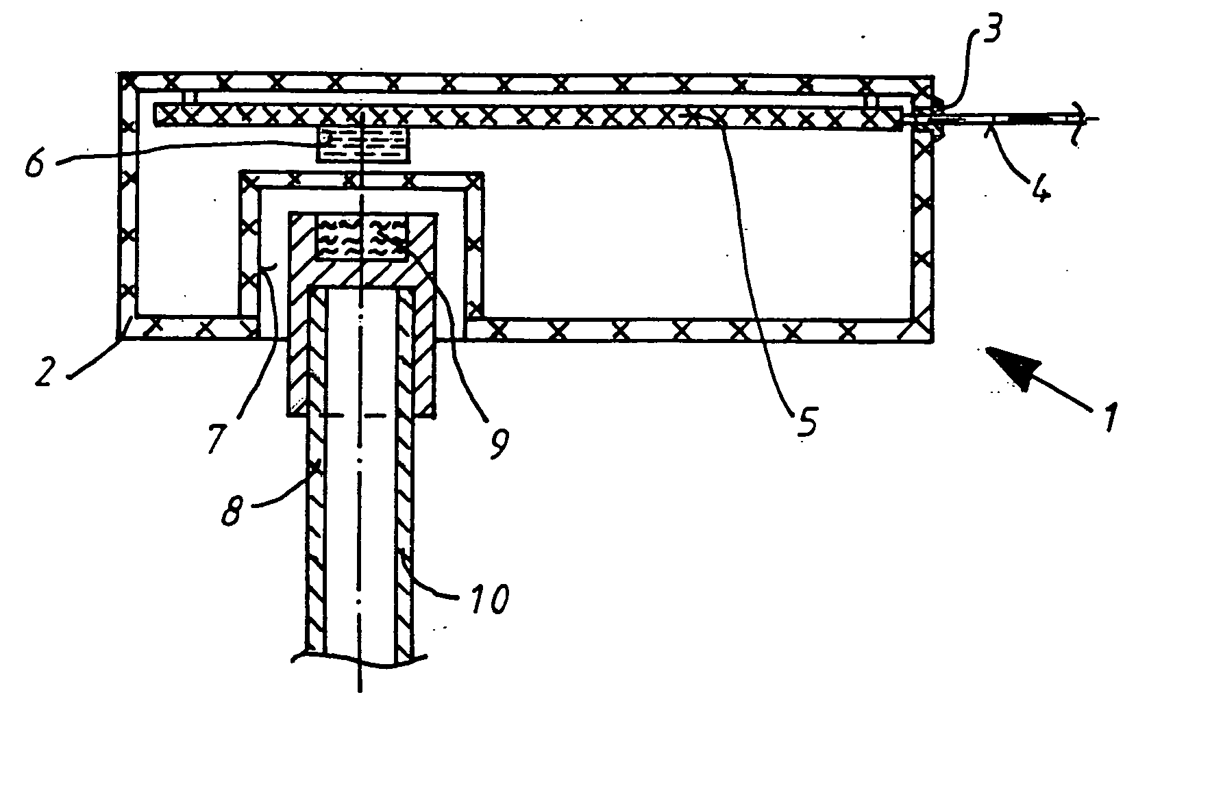
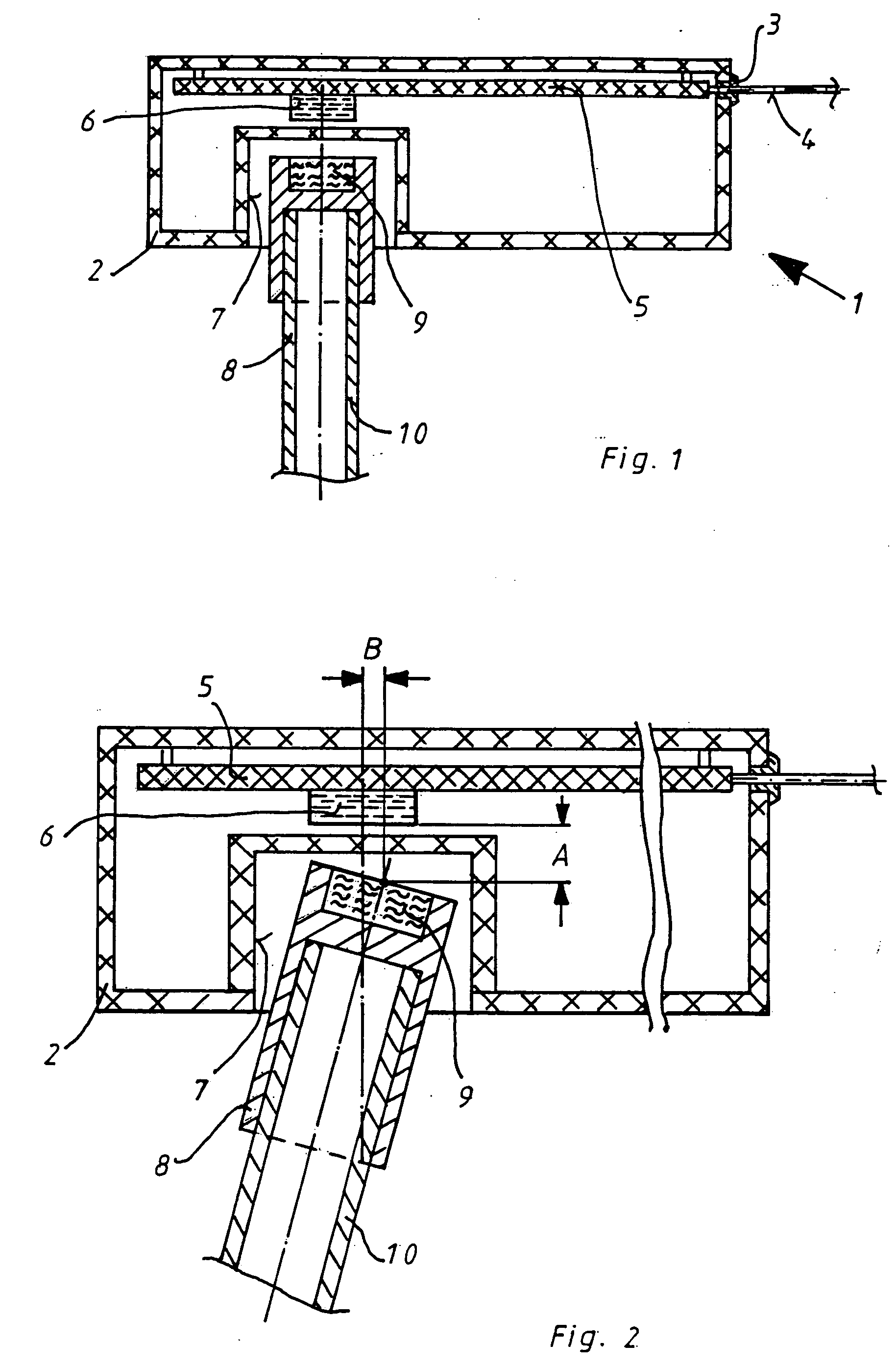
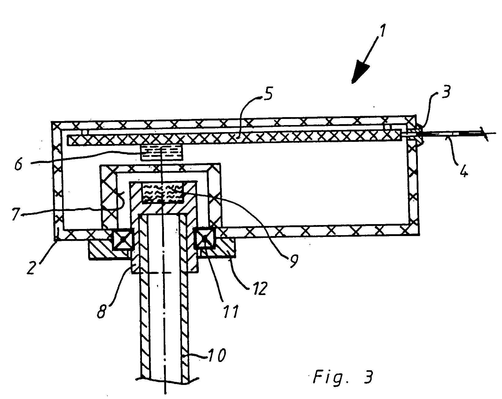
[0075] Referring now in detail to the drawings, FIG. 1 shows a position transmitter 1 having a housing 2, which is completely closed and is made of plastic. Only one sealed line insertion 3 for a cable 4 is provided. A board 5 is disposed in housing 2, which board carries an AMR sensor unit 6. A recess 7 is provided in housing 2, in which a magnet carrier 8 is mounted without contact, with a magnet 9 disposed in magnet carrier 8. Magnet carrier 8 is disposed on a shaft 10, the number of revolutions of which is supposed to be determined.

[0076] Magnet carrier 8 is disposed in recess 7 without contact. Because of the contact-free arrangement, a relatively great tolerance range is present in the interplay between magnet 9 and sensor unit 6.

[0077] As is evident in FIG. 2, a tolerance is possible in the case of contact-free mounting of magnet carrier 8 in recess 7. For example, it is possible to select the axial distance (A) at up to five millimeters with a magnetic field of 50 milliTes...


PUM


Abstract

A position transmitter for determining a position of a rotating shaft, has an AMR sensor unit or a GMR sensor unit which, for determining the position, has only one magnet disposed on a shaft to be monitored, whereby the position transmitter can be used as a single-turn and a multi-turn unit. Furthermore, a method for determining a position of a rotating shaft with the position transmitter is also provided. In accordance with the method, signals are produced using a diametrically magnetized magnet in a sensor unit, so that sine and cosine signals are obtained as output signals of the AMR sensor unit, the sine and cosine signals are digitalized, and these signals are processed by a microcontroller, with regard to the detection and evaluation of the angle of rotation, for detecting, filtering, and evaluating the number of revolutions, for detection of the direction of rotation or for data transmission of the angle of rotation and the number of revolutions to an overriding control.

Description

BACKGROUND OF THE INVENTION CROSS REFERENCE TO RELATED APPLICATIONS [0001] Applicants claim priority under 35 U.S.C. §119 of European Patent Application No. 04 / 016309.9, filed Jul. 12, 2004, and German Utility Model Application No. 20 2004 010 921.2, filed Jul. 12, 2004. [0002] 1. Field of the Invention [0003] The present invention relates to a position transmitter as well as a method for determining a position of a rotating shaft. [0004] 2. The Prior Art [0005] The state of the art (DE 198 49 108 C2, EP 0 995 974 A1) includes a rotation transmitter having a transmitter shaft that carries a first coding disk for a single-turn measurement and a second coding disk for a multi-turn measurement. Evaluation electronics are assigned to the multi-turn coding disk, which electronics pass the signals triggered by the sensor to a logic module and a subsequent counter module, which converts the signals into counter pulses. [0006] This rotation transmitter that belongs to the state of the art h...

Claims


Application Information

Patent Timeline
IPC IPC(8): G01B7/14
CPCG01D5/145
Inventor HEINZE, FRIEDERSCHAFER, DIRK
Owner FEIG ELECTRONICS MBH
Why Eureka
Try Eureka