Security element for electronic surveillance of articles

Inactive Publication Date: 2006-01-12
CHECKPOINT SYST INT
View PDF6 Cites 5 Cited by
  • Summary
  • Abstract
  • Description
  • Claims
  • Application Information

AI Technical Summary

Benefits of technology

[0012] The increase in the effective volume Veff reduces the sensitivity of the surveillance system to disturbances, enables the columns to be arranged at a greater relative distance, or it increases the detection rate of the surveillance system under otherwise like conditions. With the configuration of the security element according to the invention, the effective volume Veff is increased by about 20% as compared to known RF security elements.
[0013] In one embodiment of the invention a dielectric layer is provided between the lower conducting track and the upper conducting track except in the contact zone, thereby reliably preventing an electrical connection between the conductors at a place other than the contact zones. Particularly advantageously, the dielectric layer is constructed as an adhesive layer, a dielec

Problems solved by technology

The disadvantage of this solution is the increased cost for the security element and, in addition, the difficulty encountered in equipping merchandise of small outer dimensions with such large security elements.
Another disadvantage of the known RF security elements is the risk of the resonant frequency of the

Method used


Image

  • Security element for electronic surveillance of articles
  • Security element for electronic surveillance of articles

Examples


Embodiment Construction

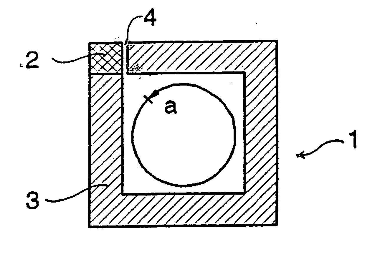
[0021]FIG. 1 shows a plan view of a lower conducting track 1. The lower conducting track 1 is stamped out from an aluminum foil of a thickness of about 38 μm. The lower conducting track 1 has a contact zone 2 within which electrical contact exists between the lower conducting track 1 and an upper conducting track not shown in FIG. 1.

[0022] Starting from the contact zone 2, the lower conducting track 1 is wound in the counterclockwise direction. The angle of rotation “a” included by the coil turn 3 is less than 2π.

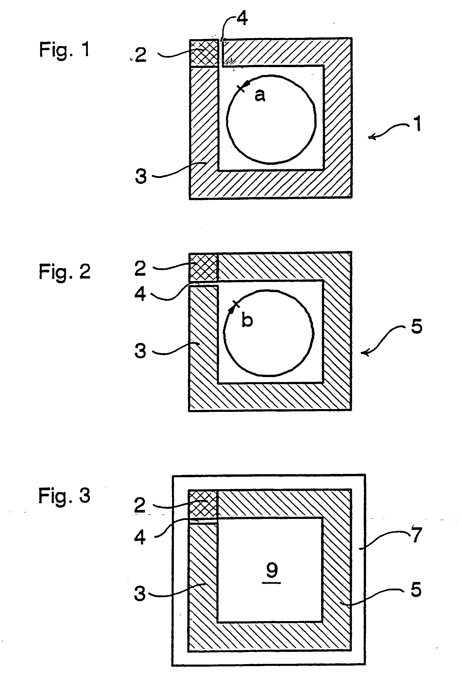
[0023]FIG. 2 shows a plan view of an upper conducting track 5. The upper conducting track 5 is likewise stamped out from an aluminum foil and has the same dimensions as the lower conducting track 1. With the security element assembled, the contact zone 2, which is also provided on the upper conducting track 5, establishes an electrical connection between the lower conductor 1 and the upper conductor 5. The upper conducting track 5 is wound in the clockwise direction, with...


PUM


Abstract

A radio frequency security element is provided for electronic surveillance of articles of merchandise. The security element comprises a lower strip conductor (1) and an upper strip conductor (5), which are wound in opposite directions. The upper and lower strip conductors and superimposed and connected in a common contact zone. The coil turns of the two conductor strips each have an included angle of rotation less than 2π. The security element has an improved detection rate and is particularly stable against changes in the resonance frequency.

Description

CROSS-REFERENCE TO RELATED APPLICATIONS [0001] This application is a continuation of International Application No. PCT / EP00 / 09522, filed Sep. 28, 2000, the disclosure of which is incorporated herein by reference. BACKGROUND OF THE INVENTION [0002] This invention relates to a security element for electronic article surveillance. [0003] German published patent application DE 197 08 180 A1, for example, discloses a suitable security element comprising one lower conducting track and one upper conducting track, wherein the conducting tracks have a contact zone and, connected thereto, respective coil turns (windings) with opposite winding directions. The conducting tracks are superimposed, and an electrical connection exists between the lower conducting track and the upper conducting track in the area of the contact zone. The entire security element has at least one coil turn with an included angle of rotation of 2π. Security elements of this type are referred to as resonant circuits or r...

Claims


Application Information

Patent Timeline
IPC IPC(8): G08B13/14G08B13/24G08B13/26H01F5/00
CPCG08B13/2431G08B13/2414
Inventor ALTWASSER, RICHARD
Owner CHECKPOINT SYST INT
Why Eureka
Try Eureka