Calibration of an interactive display system

an interactive display and calibration technology, applied in the field of optical calibration of an object sensing system, can solve the problems of vision system, barrel distortion, trapezoidal distortion, etc., and achieve the effect of accurate detection

Inactive Publication Date: 2006-01-12
MICROSOFT TECH LICENSING LLC
View PDF5 Cites 93 Cited by
  • Summary
  • Abstract
  • Description
  • Claims
  • Application Information

AI Technical Summary

Benefits of technology

[0007] The present invention was thus developed for use in calibrating and compensating errors in an interactive display system that includes a projector for projecting images on a display surface, a light source for illuminating an object on the display surface, and a vision sensing system having an imaging sensor for receiving light reflected back from the display surface by an object in contact with the display surface. In one aspect of the invention that is directed to a method, a signal is received from the imaging sensor that varies in response to the intensity of light reflected from the object in contact with the display surface. The signal received from the imagin

Problems solved by technology

However, there will inevitably be variations in the way that specific interactive display systems operate due to the inevitable manufacturing tolerances and differences in the environment that can produce thermal expansion changes, etc.
O

Method used


Image

  • Calibration of an interactive display system
  • Calibration of an interactive display system
  • Calibration of an interactive display system

Examples


Embodiment Construction

Exemplary Computing System for Implementing Present Invention

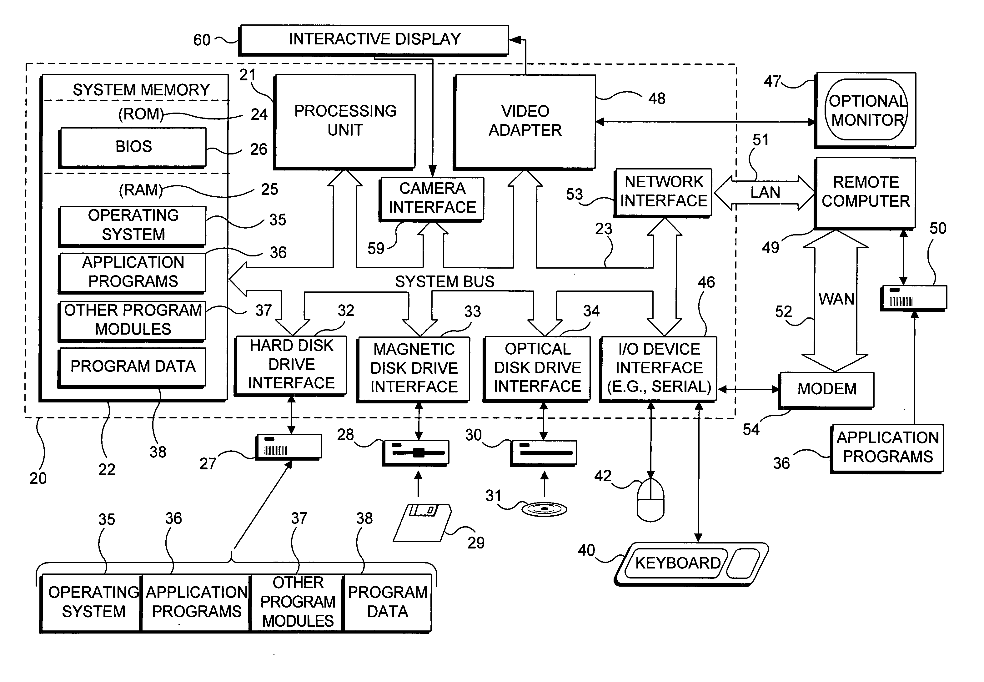
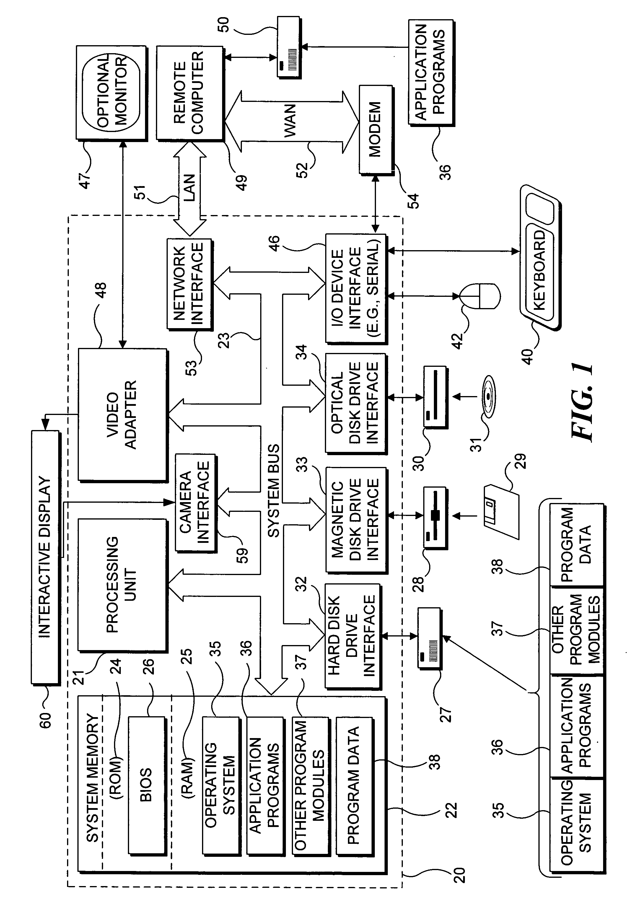
[0032] With reference to FIG. 1, an exemplary system suitable for implementing various portions of the present invention is shown. The system includes a general purpose computing device in the form of a conventional PC 20, provided with a processing unit 21, a system memory 22, and a system bus 23. The system bus couples various system components including the system memory to processing unit 21 and may be any of several types of bus structures, including a memory bus or memory controller, a peripheral bus, and a local bus using any of a variety of bus architectures. The system memory includes read only memory (ROM) 24 and random access memory (RAM) 25. A basic input / output system 26 (BIOS), containing the basic routines that help to transfer information between elements within the PC 20, such as during start up, is stored in ROM 24. PC 20 further includes a hard disk drive 27 for reading from and writing to a hard disk ...


PUM


Abstract

In an interactive display system, a projected image on a display surface and a vision system used to detect objects touching the display surface are aligned, and optical distortion of the vision system is compensated. Also, calibration procedures correct for a non-uniformity of infrared (IR) illumination of the display surface by IR light sources and establish a touch threshold for one or more uses so that the interactive display system correctly responds to each user touching the display surface. A movable IR camera filter enables automation of the alignment of the projected image and the image of the display surface and help in detecting problems in either the projector or vision system.

Description

FIELD OF THE INVENTION [0001] This invention generally relates to the optical calibration of an object sensing system used in connection with an interactive table on which images are projected, and more specifically, pertains to compensating for optical distortion produced by an infrared (IR) source and camera used for sensing objects resting on the interactive table, and to determining a touch threshold in regard to reflectance of IR from a user's fingertip that is contact with a surface of the interactive table. BACKGROUND OF THE INVENTION [0002] Touch responsive displays are used on personal data assistants (PDAs), tablet personal computers (PCs), and as monitors that can be coupled to PCs. However, most such displays are simply pressure activated or employ optical sensors around the periphery of the display surface. Another type of touch sensitive display has been developed in the art that uses optical vision systems for interactively detecting an object touching a display surfa...

Claims


Application Information

Patent Timeline
IPC IPC(8): G09G5/00G06F3/033G06F3/041
CPCG06F3/0418G06F3/0425
Inventor WILSON, ANDREW D.YEE, DAWSON L.
Owner MICROSOFT TECH LICENSING LLC
Why Eureka
Try Eureka