High efficacy waveguide coupler

a waveguide and high-efficiency technology, applied in the field of optical couplers, can solve the problems of increasing brightness, reducing cost, and reducing power consumption

Active Publication Date: 2006-01-12
OREE ADVANCED ILLUMINATION SOLUTIONS LTD +1
View PDF12 Cites 86 Cited by
  • Summary
  • Abstract
  • Description
  • Claims
  • Application Information

AI Technical Summary

Benefits of technology

[0075] According to still another aspect of the present invention there is...

Problems solved by technology

Display technologies such as liquid crystal display (LCD) do not produce light within the pixel and the pixel is only able to block light.
When the divergence angle complies with the propagation angle a larger portion of the light reaches the user, thus decreasing power consumption, increasing brightness, decreasing cost, and practically affecting all the parameters of the quality of the picture.
However, most of the light sources emit light over a divergence angle that is too large for all the light to be successfully coupled to the waveguide.
Aside for the additional ...

Method used


Image

  • High efficacy waveguide coupler
  • High efficacy waveguide coupler
  • High efficacy waveguide coupler

Examples


example

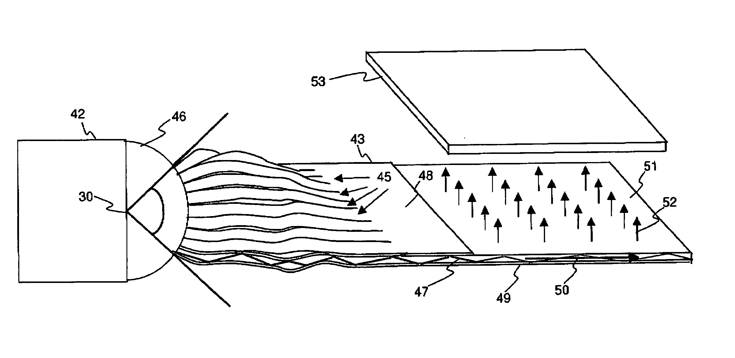
[0124] A backlight for a display having a of 2.1 inch, a length of 42.672 mm of and a width of 32.004 mm is connected to a light source such as a LED that has a divergence angle of 25 degrees. The waveguide is coupled to the light source via 15 light-guides attached to the waveguide's core (n2) layer.

[0125] The waveguide's clading material had refractive index of n1=1.48.

[0126] The waveguide's core layer and strips has refractive index of n2=10.51.

[0127] The waveguide's propagation angle is 11.44 degrees and the numerical aperture is 0.1983.

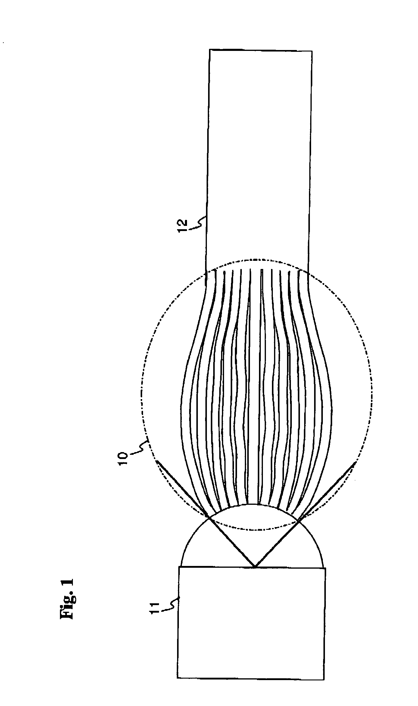
[0128] A lens is mounted between the LED and the light-guides (strips).

[0129] The coupling efficiency, that is the percentage of the light received by the waveguide at the output of the coupler, from the light emitted from the LED at the output to the coupler, is 70.98%.

[0130] The following table presents the calculations of the system from a standard energy source via the input into the strips, strips transmission losses, waveguide transmi...


PUM


Abstract

An optical coupling apparatus for coupling a waveguide to a light source, when the light source emits light at a divergence angle that is larger than the critical angle of the waveguide. The optical coupler comprises a plurality of light-guides, preferably cut from the edge of the waveguide. The light-guides are arranged to connect the waveguide to the light source via a plurality of orientations so that the entire divergence angle is covered within the critical angle of the light-guides.

Description

RELATIONSHIP TO EXISTING APPLICATIONS [0001] The present application claims priority from a U.S. provisional patent application 60 / 580,705 filed Jun. 21, 2004, the contents of which are hereby incorporated by reference.FIELD AND BACKGROUND OF THE INVENTION [0002] The present invention relates to optical couplers, and, more particularly, but not exclusively to coupling between a source of light and a waveguide. [0003] There is a growing demand for a large variety of display devices. Sophisticated display devices serve a growing number of applications with diverse requirements. There is a continuous pressure to improve covering all the aspects of the display. [0004] In cathode ray tubes (CRT), plasma displays, light emitting diode (LED) displays, etc. each pixel radiates light independently. Display technologies such as liquid crystal display (LCD) do not produce light within the pixel and the pixel is only able to block light. Therefore a LCD display requires illumination behind the ...

Claims


Application Information

Patent Timeline
IPC IPC(8): G02B6/26
CPCG02B6/04G02B6/0028
Inventor MEIR, NOAMFINE, ERAN
Owner OREE ADVANCED ILLUMINATION SOLUTIONS LTD
Why Eureka
Try Eureka