
Method of manufacturing flash memory device

a manufacturing method and flash memory technology, applied in the direction of semiconductor devices, basic electric elements, electrical appliances, etc., can solve the problems of difficult to obtain the overlay margin uniformity across the entire wafer, difficult to secure the overlay margin between the active region and the floating gate through an existing sti process and an existing floating gate mask process, etc., to achieve the effect of improving the reliability reducing the size and improving the processional stability of the flash memory devi

Inactive Publication Date: 2006-01-12
STMICROELECTRONICS SRL +1
View PDF0 Cites 34 Cited by
  • Summary
  • Abstract
  • Description
  • Claims
  • Application Information

AI Technical Summary

Benefits of technology

[0007] Accordingly, the present invention has been made in view of the above problems, and it is an object of the present invention to provide a method of manufacturing a flash memory device in which an overlay margin between an active region and a floating gate is secured, the overlay margin uniformity is obtained across the entire wafer, and generation of moats at the boundary between an isolation film and the active region across the entire wafer is prevented, whereby reliability of the flash memory device is improved, processional stability of the flash memory device is secured and the size of the flash memory device can shrink.

Problems solved by technology

As the flash memory device gradually shrinks, however, it is difficult to secure the overlay margin between the active region and the floating gate through an existing STI process and an existing floating gate mask process.
It is also difficult to obtain the overlay margin uniformity across the entire wafer.
If the wet etching process is performed excessively, moats are generated at the boundary between the trench type isolation film and the active region.
This makes a subsequent process difficult.
Although an etch target of the wet etching process is properly set in order to solve this problem, it is difficult to obtain a uniform isolation film not having moats across the entire wafer.
As such, there is a limit to the shrinkage of the flash memory device due to securing of the overlay margin between the active region and the floating gate and the moats generated at the boundary between the isolation film and the active region.

Method used


Image

  • Method of manufacturing flash memory device
  • Method of manufacturing flash memory device
  • Method of manufacturing flash memory device

Examples


Embodiment Construction

[0030] Now the preferred embodiments according to the present invention will be described with reference to the accompanying drawings. Since preferred embodiments are provided for the purpose that the ordinary skilled in the art are able to understand the present invention, they may be modified in various manners and the scope of the present invention is not limited by the preferred embodiments described later. Further, in the drawing, the thickness and size of each layer are exaggerated for convenience of explanation and clarity. Like reference numerals are used to identify the same or similar parts.

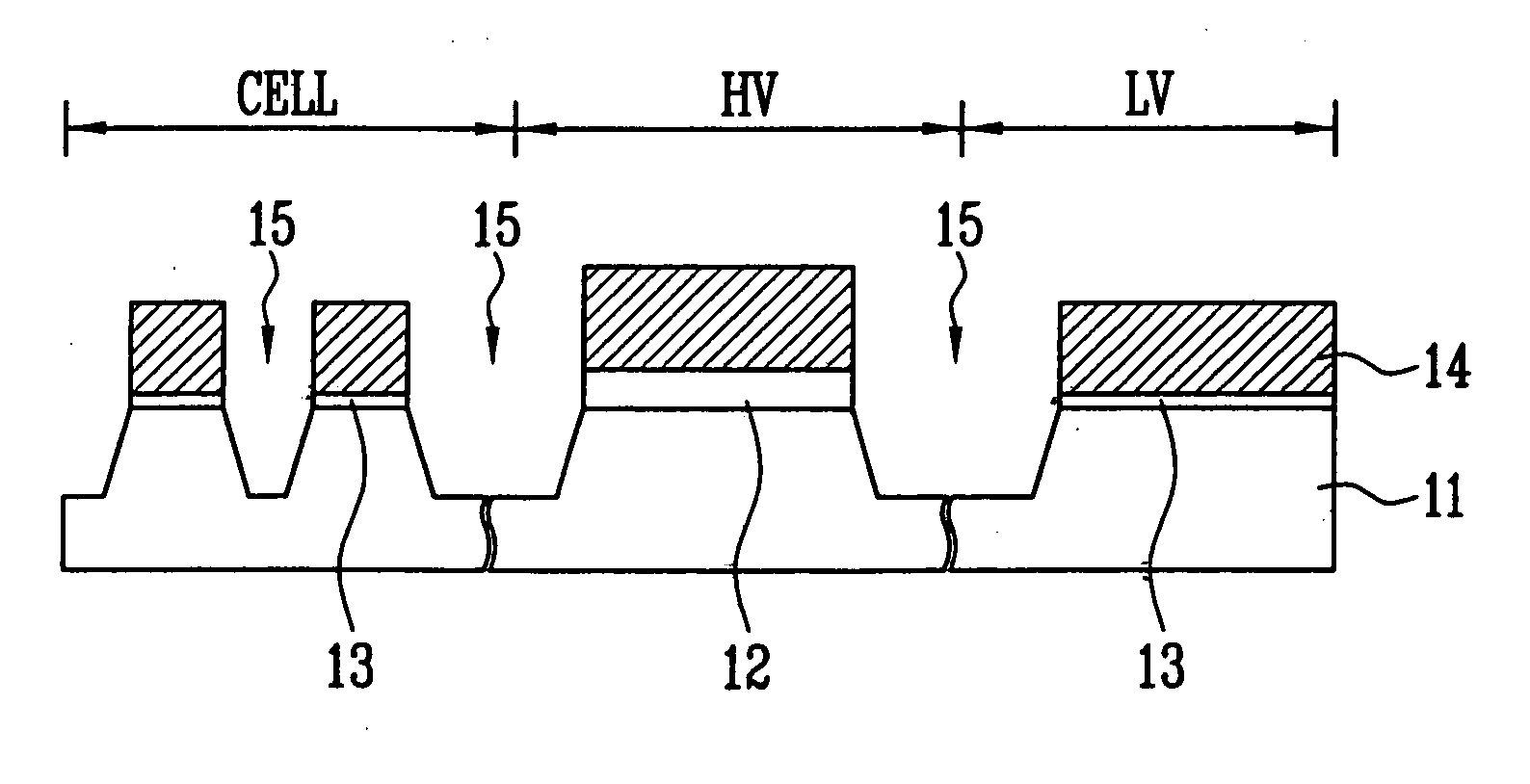
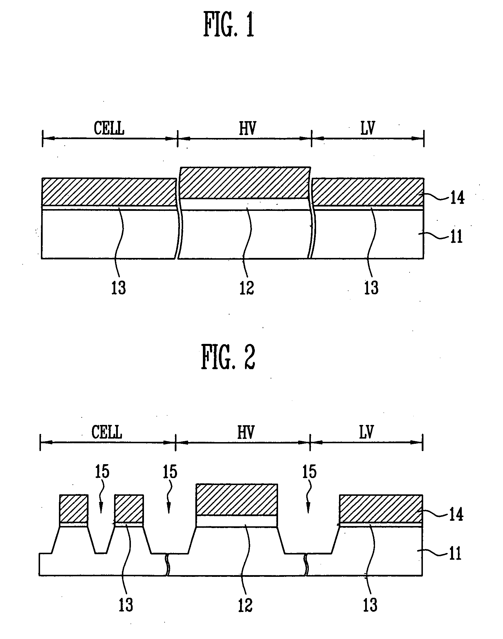
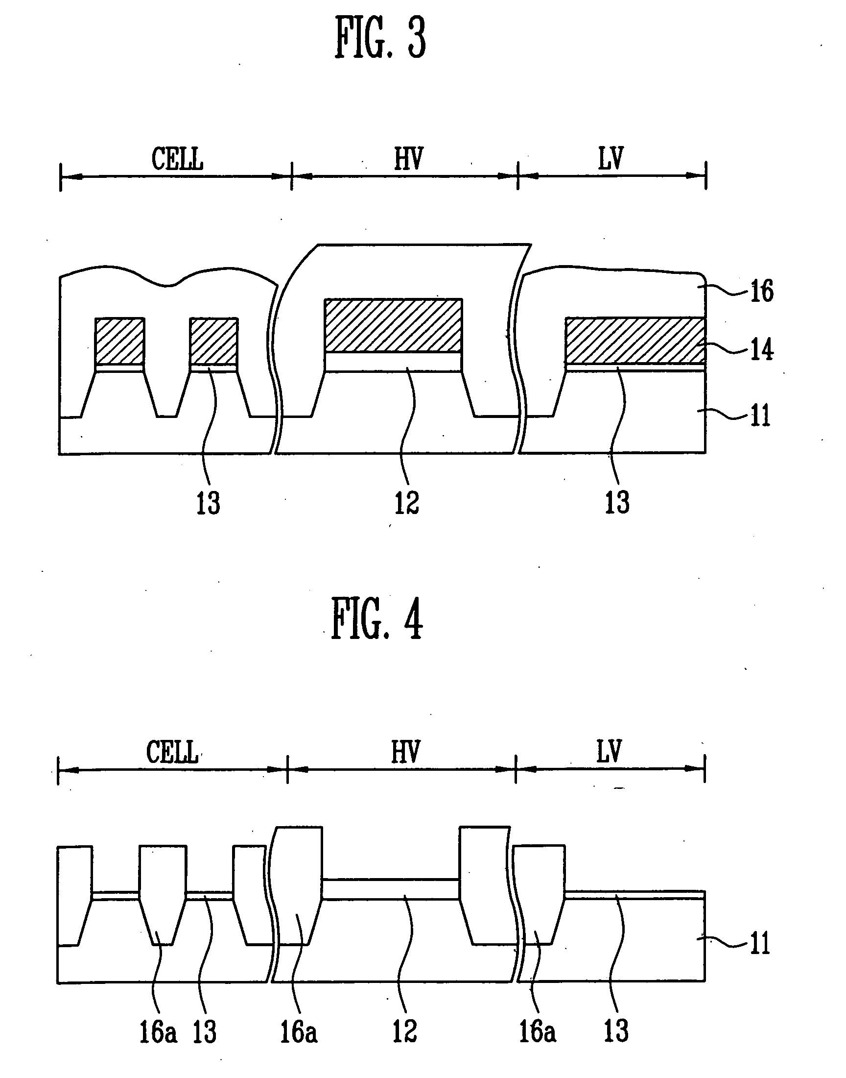
[0031] FIGS. 1 to 10 are cross-sectional views for explaining a method of manufacturing a floating gate of a flash memory device according to an embodiment of the present invention.

[0032] Referring to FIG. 1, a semiconductor substrate 11 in which a cell region CELL, a high voltage transistor region HV and a low voltage transistor region LV are defined and on which a well formation ion...


PUM


Abstract

Disclosed is a method of manufacturing a flash memory device using a STI process. Isolation films of a projection structure becomes isolation films of a nipple structure by means of a slant ion implant process and a wet etching process. A polysilicon layer is removed until the tops of the isolation films through two step processes of a CMP process and an etch-back process, thus forming floating gates and gates of high voltage and low voltage transistors of a cell. As such, as the isolation films of the nipple structure and the floating gates are formed at the same time, it is possible secure the overlay margin between an active region and the floating gates regardless of the shrinkage of the flash memory device. Also, moats can be prevented from being generated at the boundary between the active regions when the isolation films of the nipple structure are formed. Further, when the floating gates and the gates of the high voltage and low voltage transistors are formed, a dishing phenomenon and an erosion phenomenon can be prevented.

Description

BACKGROUND [0001] 1. Field of the Invention [0002] The present invention relates to a method of manufacturing a flash memory device, and more specifically, to a method of manufacturing a flash memory device in which the size of the flash memory device can shrink while improving reliability of the flash memory device through a shallow trench isolation (hereinafter, referred to as ‘STI’) process. [0003] 2. Discussion of Related Art [0004] Generally, a flash memory device is a stack gate structure consisting of a floating gate and a control gate. In the floating gate, since the active region must be covered, the overlay margin between the active region and the floating gate is an important factor. As the flash memory device gradually shrinks, however, it is difficult to secure the overlay margin between the active region and the floating gate through an existing STI process and an existing floating gate mask process. It is also difficult to obtain the overlay margin uniformity across t...

Claims


Application Information

Patent Timeline
Patent Type & Authority Applications(United States)
IPC IPC(8): H01L21/336H01L21/28H01L21/8239H01L21/8247H01L27/105H01L27/115
CPCH01L21/28273H01L27/105H01L27/1052H01L27/11526H01L27/11546H01L27/115H01L29/40114H10B41/49H10B41/40H10B69/00H10B99/00
Inventor SONG, PIL GEUNPARK, SANG WOOK
Owner STMICROELECTRONICS SRL
Learn More