Gas measurement system

Active Publication Date: 2006-01-12
RIC INVESTMENTS LLC
View PDF21 Cites 69 Cited by
  • Summary
  • Abstract
  • Description
  • Claims
  • Application Information

AI Technical Summary

Benefits of technology

[0012] Accordingly, it is an object of the present invention to provide a gas measurement system that overcomes the shortcomings of conventional gas measuring systems. This object is achieved according to one embodiment of the present invention by providing a gas measurement system that includes a beamsplitter adapted to separate infrared radiation into a first beam and a second beam, a mirror adapted to receive the first beam from the beamsplitter, a first filter adapted to rece

Problems solved by technology

Mainstream gas measurement systems known in the art transmit analog signals along a cable, typically 6 to 8 feet in length, between the host system and the gas sensor and, as such, are susceptible to electromagnetic interference (EMI).
With the measurement and signal electronics located in the host system, existing

Method used


Image

  • Gas measurement system
  • Gas measurement system
  • Gas measurement system

Examples


Embodiment Construction

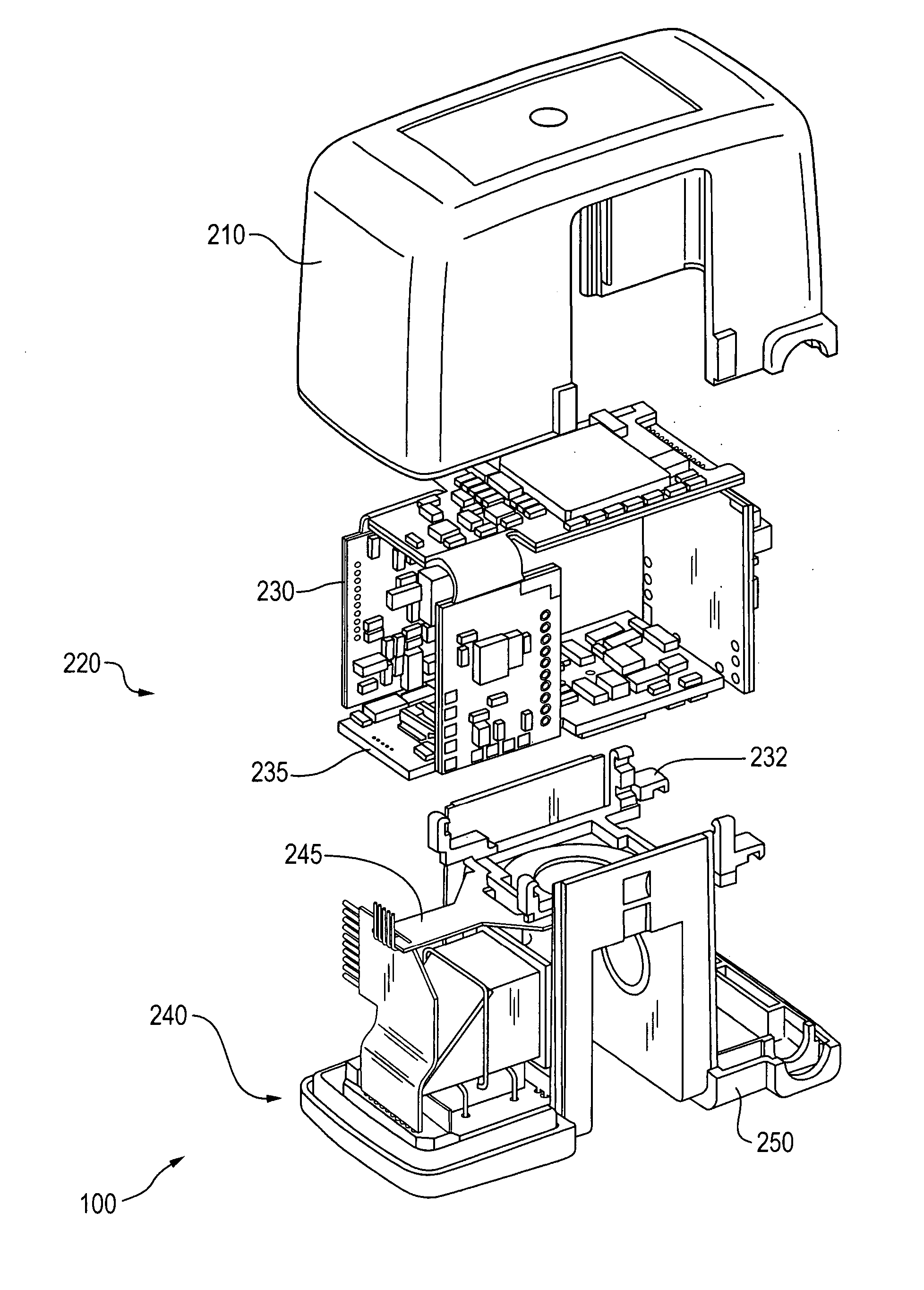
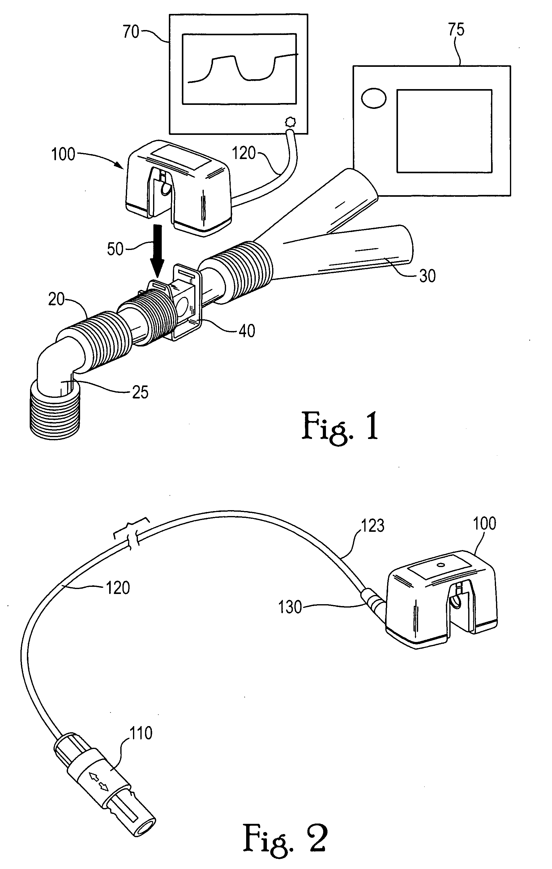
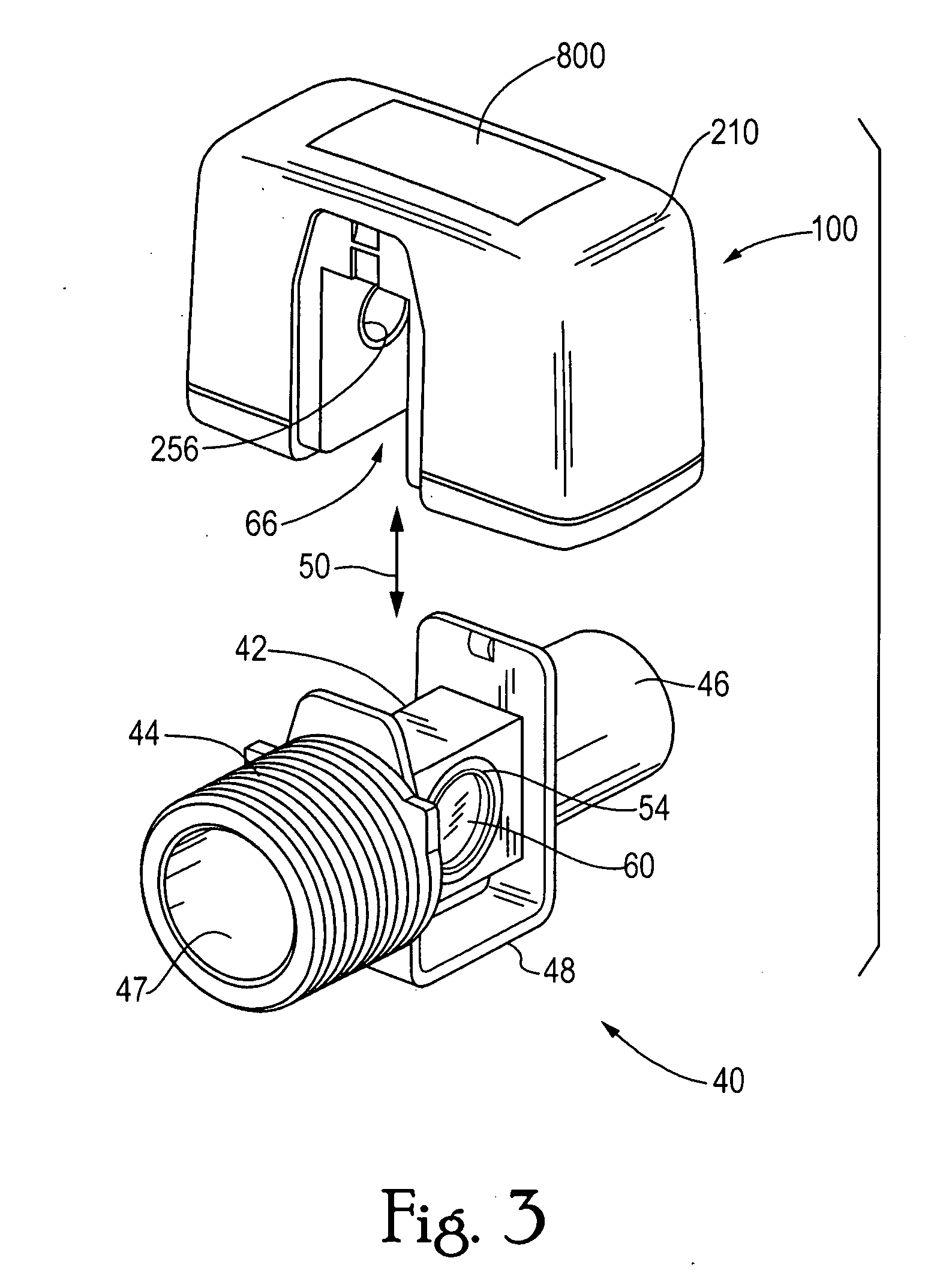
[0042] A gas measurement system 100 according to the principles of the present invention includes all of the signal and data processing required to produce continuous values of a partial pressure or concentration of a gas flowing through an airway adapter in fluid communication with a patient's airway. The gas measurement system is located on a “measurement head” that fits onto an airway adapter. The gas measurement system includes the electronic circuitry required to measure and compute a continuous value for infrared absorbing gases, such as carbon dioxide, and luminescence quenching gases, such as oxygen, and interface the gas measurement system to a host system. In an exemplary embodiment, gas measurement system 100 acquires and processes the analog signals, then transmits digitized patient parameters and waveforms through an interface cable 120 as a serialized data stream.

[0043] The gas measurement system of the present invention eliminates the need for an additional electroni...


PUM


Abstract

A gas measurement system of this invention includes a detector assembly having a beamsplitter adapted to separate infrared radiation into a first beam and a second beam and a mirror adapted to receive the first beam from the beamsplitter. The first and second beams are directed to first and second detectors that are disposed in a common plane. In one embodiment, the optical elements are provided on or in an optical block. In another embodiment, the gas measurement system includes a housing that contains an infrared absorption gas measurement assembly, a luminescence quenching gas measurement assembly, and a processor that is programmed to measure gas constituents of a gas flow based on an output of the infrared absorption gas measurement assembly and the luminescence quenching gas measurement assembly.

Description

CROSS-REFERENCE TO RELATED APPLICATIONS [0001] This application is a Continuation-In-Part under 35 U.S.C. § 120 from U.S. patent application Ser. No. 10 / 792,180, filed Mar. 3, 2004, which claims priority under 35 U.S.C. § 119(e) from provisional U.S. patent application No. 60 / 452,656 filed Mar. 7, 2003, and is also a Continuation-In-Part under 35 U.S.C. § 120 from U.S. patent application Ser. No. 10 / 781,382, filed Feb. 18, 2004, which claims priority under 35 U.S.C. § 119(e) from provisional U.S. patent application No. 60 / 449,428 filed Feb. 21, 2003, the contents of each of these applications are incorporated herein by reference.BACKGROUND OF THE INVENTION [0002] 1. Field of the Invention [0003] The present invention relates to a mainstream respiratory gas measurement system with integrated signal processing and improved optical design, and to a method of assembling such a system. [0004] 2. Description of the Related Art [0005] Respiratory gas measurement systems comprise gas sensin...

Claims


Application Information

Patent Timeline
IPC IPC(8): G01J5/02A61B5/08
CPCA61B5/083A61B2562/12G01J3/0291G01N2021/6432G01N21/3504G01N21/6428G01J3/36
Inventor DANIELS, RICH H.NELSON, RICHARDDELFAVERO, JOHN R.DAVIS, RAYMOND G.PIERRY, ANTHONY T.RUSSELL, JAMES T.
Owner RIC INVESTMENTS LLC
Why Eureka
Try Eureka