Refrigerant system with tandem compressors and reheat function

a technology of refrigerant system and compressor, which is applied in the field of refrigerant cycle, can solve the problems that refrigerant cycle with tandem compressors has not had as complete control over temperature and humidity levels, and the reheat coil has not been utilized in a combination with tandem compressors, so as to achieve greater capacity control

Inactive Publication Date: 2006-01-19
CARRIER CORP
View PDF22 Cites 17 Cited by
  • Summary
  • Abstract
  • Description
  • Claims
  • Application Information

AI Technical Summary

Benefits of technology

[0006] In disclosed embodiments of this invention, a refrigerant system incorporates tandem compressors. At least two compressors each separately compress a refrigerant and deliver it into the refrigerant cycle. A reheat coil is also incorporated into the refrigerant system, and receives air having passed over the evaporator to reheat the air to a desired temperature when required. In one embodiment, the reheat coil is positioned in the refrigerant cycle to receive a hot gas. Other embodiments may position the reheat coil such that it utilizes a two-phase mixture of refrigerant, or a liquid refrigerant. Also, some embodiments allow the condenser to be bypassed by at least a portion of refrigerant flow, when desired. Further, the reheat cycle may be incorporated in a system utilizing either economized or conventional tandem compressors, or a combination of both, in other embodiments. Also, in one embodiment, at least one compressor may be unloaded to provide even greater capacity control.

Problems solved by technology

The reheat coil has not been utilized in a combination with tandem compressors, however.
Thus, the refrigerant cycles with tandem compressors have not had as complete control over temperature and humidity levels as may be desired.

Method used


Image

  • Refrigerant system with tandem compressors and reheat function
  • Refrigerant system with tandem compressors and reheat function
  • Refrigerant system with tandem compressors and reheat function

Examples


embodiment 50

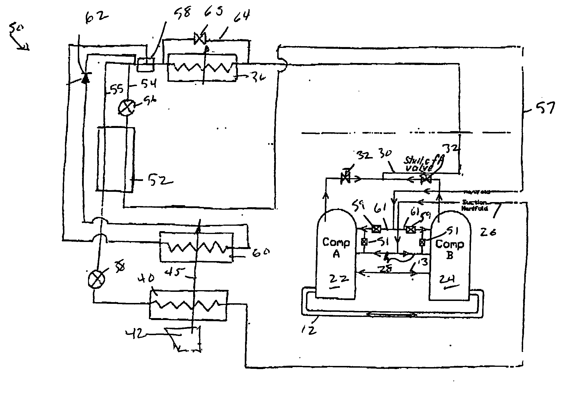
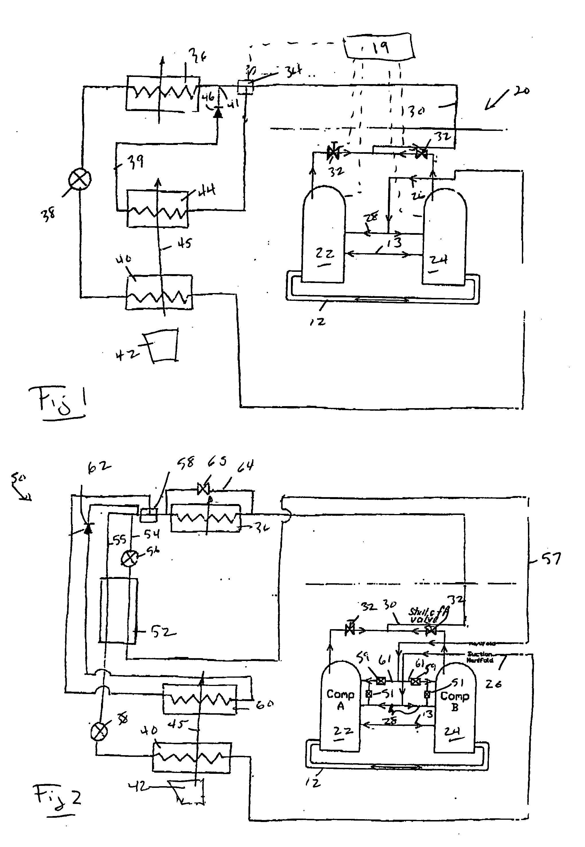
[0017]FIG. 2 shows another embodiment 50. There are tandem economized compressors 22 and 24 delivering refrigerant to a discharge manifold 30. Downstream of this manifold is a condenser 36, a main expansion device 38, and an evaporator 40. An air moving device 42 blows air over evaporator 40. Refrigerant is returned to a suction manifold 26, and through lines 28 back to the individual suction ports of compressors 22 and 24. Compressors 22 and 24 also have intermediate pressure, or economizer, ports communicating through lines 61 and economizer manifold 57 to the refrigerant system. Economizer lines 61 may incorporate shutoff valves 59 in order to switch between economizer and conventional modes of operation for each individual compressor. Bypass valves 51 allow the compressors to be unloaded, such that either or both of the compressors can be operated at a reduced capacity.

[0018] An economizer loop is incorporated in the refrigerant system 50 downstream of the condenser 36. In the e...

embodiment 70

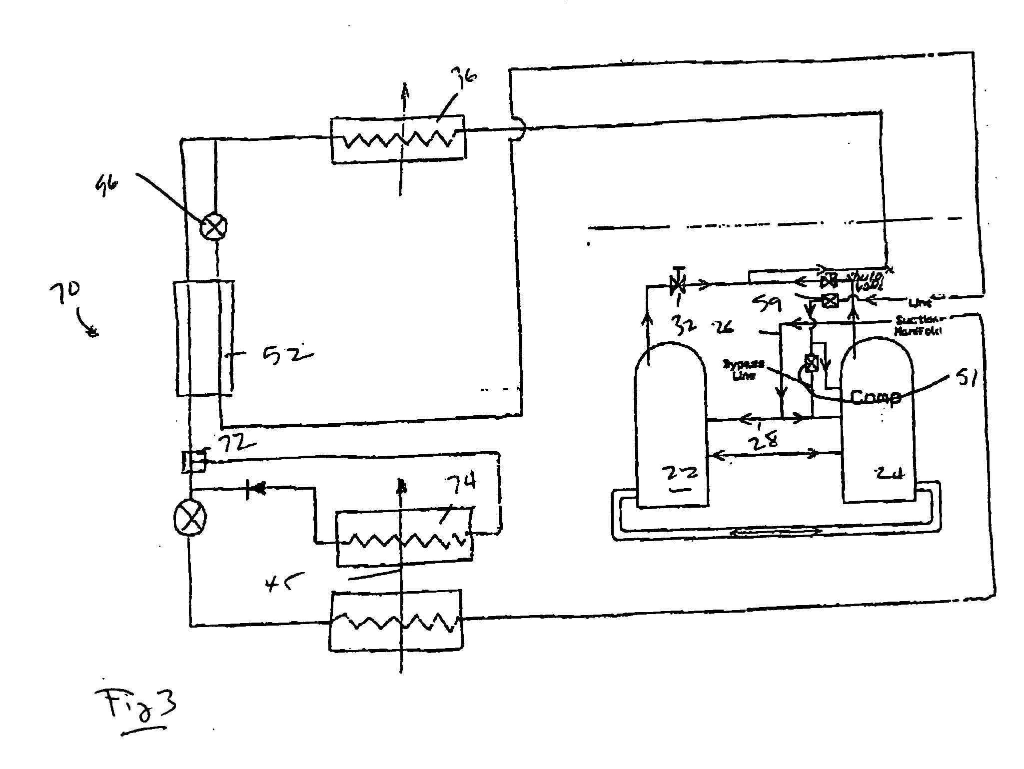
[0025]FIG. 3 shows yet another embodiment 70. In embodiment 70, the reheat coil 74 communicates with the main cycle refrigerant by means of a three-way valve 72 downstream of the economizer heat exchanger 52. Thus, there would be a warm liquid refrigerant circulated through the reheat coil. Further, the compressors 22 and 24 are provided with a bypass line through valve 51 on only one of the two compressors (here compressor 24). Further, the economizer fluid is returned through line 28 to only one of the two compressors (here compressor 24 as well). While this embodiment does not provide the extreme number of steps of control provided by FIG. 2 embodiment, it does provide additional control when compared to a system that does not have tandem compressors, an economizer cycle or a reheat coil. The two tandem compressors 24 and 22 can still be operated independently, or in combination. The economizer cycle would only be utilized in combination with operation of compressor 24. Any numbe...


PUM


Abstract

A refrigerant system incorporates at least two compressors that act in tandem to provide variable control over the refrigerant system performance. The tandem compressors can be of conventional or economized type and are configured for maximum performance utilization. Further, a reheat circuit can be incorporated into the refrigerant system at several different locations. The reheat cycle provides additional control over sensible and latent capacity of the refrigerant system, and is particularly advantageous when utilized in combination with the tandem compressors. As a result, multiple steps of unloading can be implemented in all operation regimes, the external load demands are satisfied with much greater precision, eliminating undesirable variations in temperature and humidity, system efficiency and reliability are augmented and equipment life-cycle cost is reduced.

Description

BACKGROUND OF THE INVENTION [0001] This invention relates to refrigerant cycles incorporating a reheat coil, and wherein a tandem compressor arrangement is utilized. The resulting cycles provide an enhanced control over both humidity and temperature in the conditioned space as well as improve efficiency, reliability and life-cycle cost of the equipment. [0002] Refrigerant cycles are utilized to change the temperature and humidity, or otherwise control the environment, in the conditioned space. In particular, a refrigerant cycle will typically include a compressor delivering a compressed refrigerant to a condenser, and from the condenser to an expansion device. The refrigerant exchanges heat with an outdoor environment at the condenser, and is expanded in the expansion device to a lower pressure and temperature. From the expansion device, the refrigerant continues to an evaporator at which it exchanges heat with an indoor environment, or an environment to be conditioned. From the eva...

Claims


Application Information

Patent Timeline
Patent Type & Authority Applications(United States)
IPC IPC(8): F25B29/00F25B1/10F25B41/00
CPCF24F3/153F25B2400/13F25B2400/075F25B41/04F25B41/20F25B41/24
Inventor TARAS, MICHAEL F.LIFSON, ALEXANDER
Owner CARRIER CORP
Why Eureka
Try Eureka