

Powerless voltage automatic control system for area power grid
A technology of automatic voltage control and regional power grid, applied in the direction of AC network voltage adjustment, reactive power compensation, etc., can solve the problem of not realizing the horizontal and vertical coordination of grid reactive power, and reduce labor intensity, network loss and operating cost. , The effect of improving the voltage qualification rate
- Summary
- Abstract
- Description
- Claims
- Application Information
AI Technical Summary
Problems solved by technology
Method used
Image

Examples
Embodiment Construction
[0029] The embodiments of the present invention are described in detail below in conjunction with the accompanying drawings: this embodiment is implemented on the premise of the technical solution of the present invention, and detailed implementation methods and specific operating procedures are provided, but the protection scope of the present invention is not limited to the following the described embodiment.
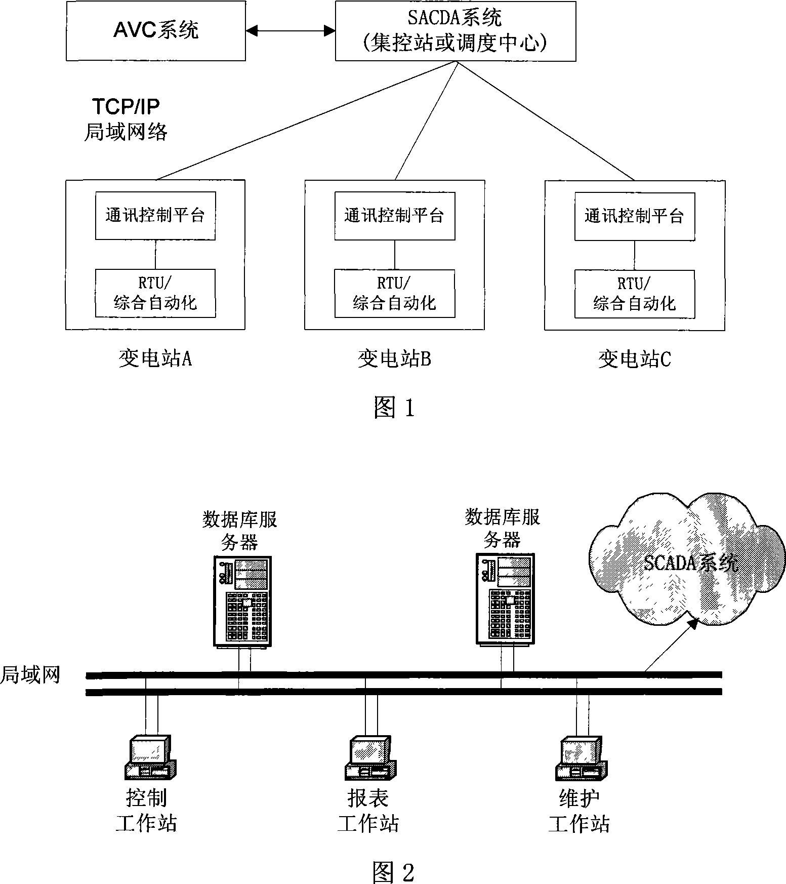
[0030] As shown in Fig. 1, the system of this embodiment is located in the dispatching center or centralized control center, and realizes the control of the substation capacitor bank and transformer tap through the SCADA system.
[0031] As shown in Figure 2, when this embodiment is applied, two servers and three workstations are used, wherein the servers use the UNIX operating system, and the workstations use the NT operating system.
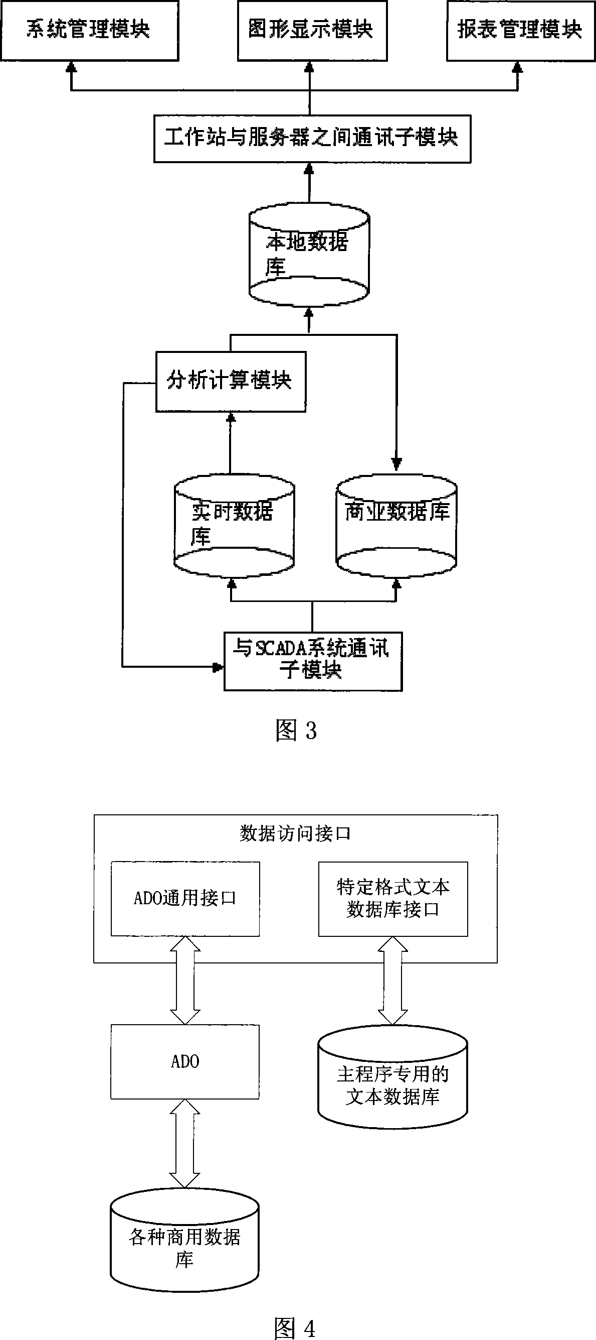
[0032]As shown in Figure 3, this embodiment is composed of a database module, a communication module, an analysis and calculation mod...
PUM
 Abstract
Description
Claims
Application Information