
Integration of biochemical protocols in a continuous flow microfluidic device

a microfluidic device and biochemical technology, applied in the direction of fluid speed measurement, fluid pressure measurement by electric/magnetic elements, optical light guides, etc., can solve the problems of not allowing large-scale protocols to be performed, integrating the mixing of reagents, and movement of fluids, so as to reduce the number of distributions, improve throughput, and reduce costs

Inactive Publication Date: 2006-01-19
COMMISSARIAT A LENERGIE ATOMIQUE ET AUX ENERGIES ALTERNATIVES
View PDF26 Cites 30 Cited by
  • Summary
  • Abstract
  • Description
  • Claims
  • Application Information

AI Technical Summary

Benefits of technology

The present invention provides a device and method for conducting biochemical or chemical processes on samples using a microfluidic substrate with at least one microchannel for carrying out the protocol. The device includes a microfluidic substrate with at least one microchannel, a thermal support, and a force supplying member for controlling the temperature. The device can be used in a continuous flow mode, allowing for the execution of the protocol in different zones of the channel. The device can also be used in parallel channels to improve throughput and reduce costs. The method involves feeding a continuous flow of a solution containing the sample and injecting reagents, while transferring heat between the thermal support and the sample. The device and method provide automated control over the reaction temperature, movement of the fluids, and detection of the sample.

Problems solved by technology

This device does not, however, integrate the mixing of reagents, and it does not allow large scale protocols to be performed.
One of the difficulties in implementing these devices resides in the movement of the fluids.
These systems which integrate electrodes, microvalves or micropumps are very costly and their complexity does not allow large scale applications for simultaneously treating a very large number of samples.
One of the major difficulties is the distribution, mixing and transport of a very large number of products in parallel or in series.

Method used


Image

  • Integration of biochemical protocols in a continuous flow microfluidic device
  • Integration of biochemical protocols in a continuous flow microfluidic device
  • Integration of biochemical protocols in a continuous flow microfluidic device

Examples


example 1

PCR Reaction in a Continuos Flow in a Microfluidic Device

[0337] A PCR reaction mixture was run through a channel in which a PCR was performed.

[0338] The microfluidic substrate comprised 10 channels in parallel chemically etched in silicone. The channels were rectilinear with a diameter of the order of about 600 μm in the reaction zones. The surface area of the section of a channel was of the order of about 0.25 mm2.

[0339] The PCR was carried out in parallel in 3 channels. The volume of one PCR reaction was 1.2 μl, but ten identical PCR reactions (12 μl (10×1.2 μl)) were performed for out of the device post PCR sample analysis (quantification and size analysis).

[0340] The microfluidic substrate was siliconized just before the substrate was used. Before the PCR reaction, all the channels were filled with previously degassed and filtered water. A high flow rate of the order of 25 μl / min was applied for 15 minutes to remove all the air bubbles present in the circuits. A previously d...

example 2

Integration of a Genotyping Protocol in a Continuous Flow Microfluidic Device

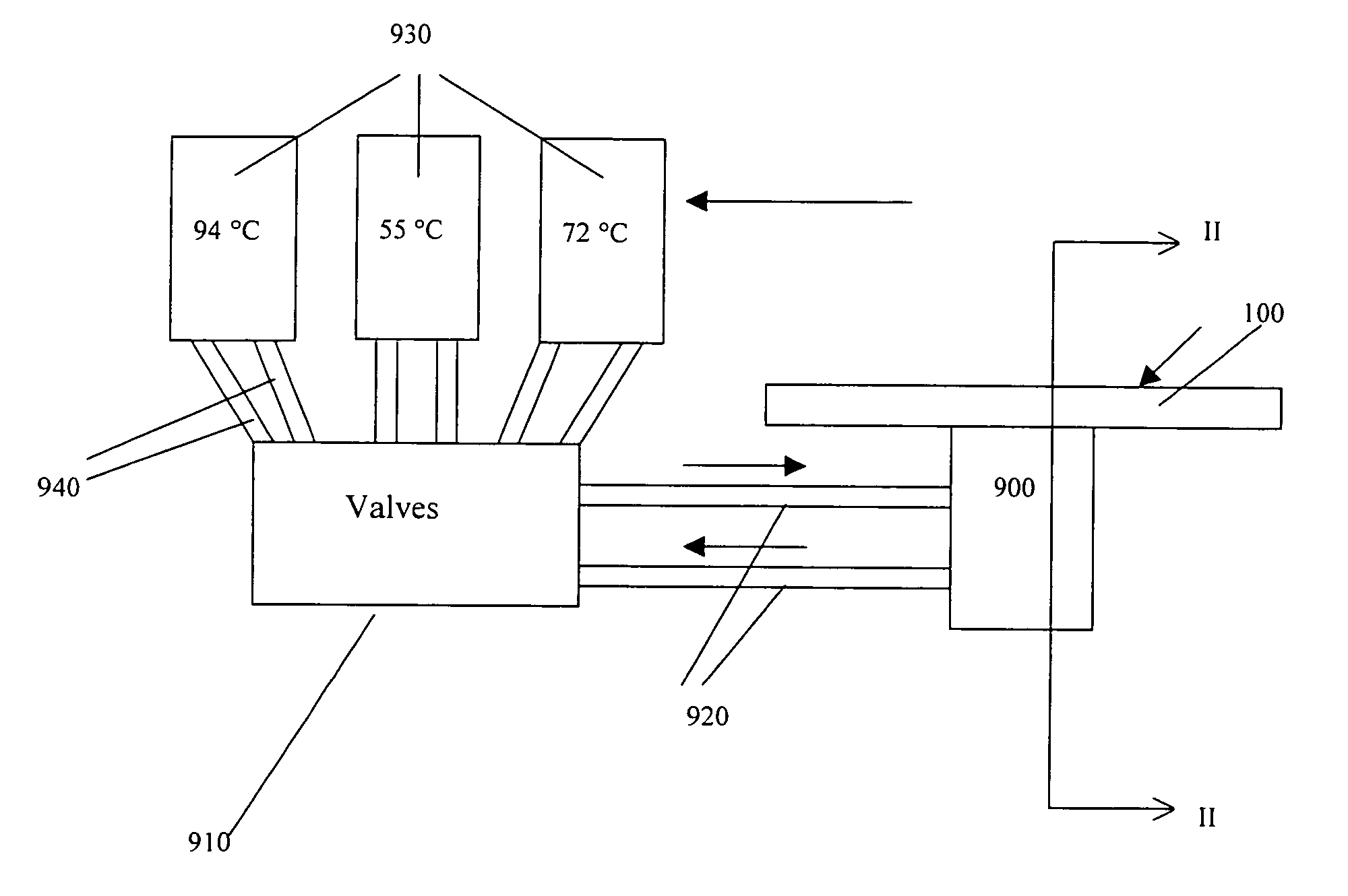
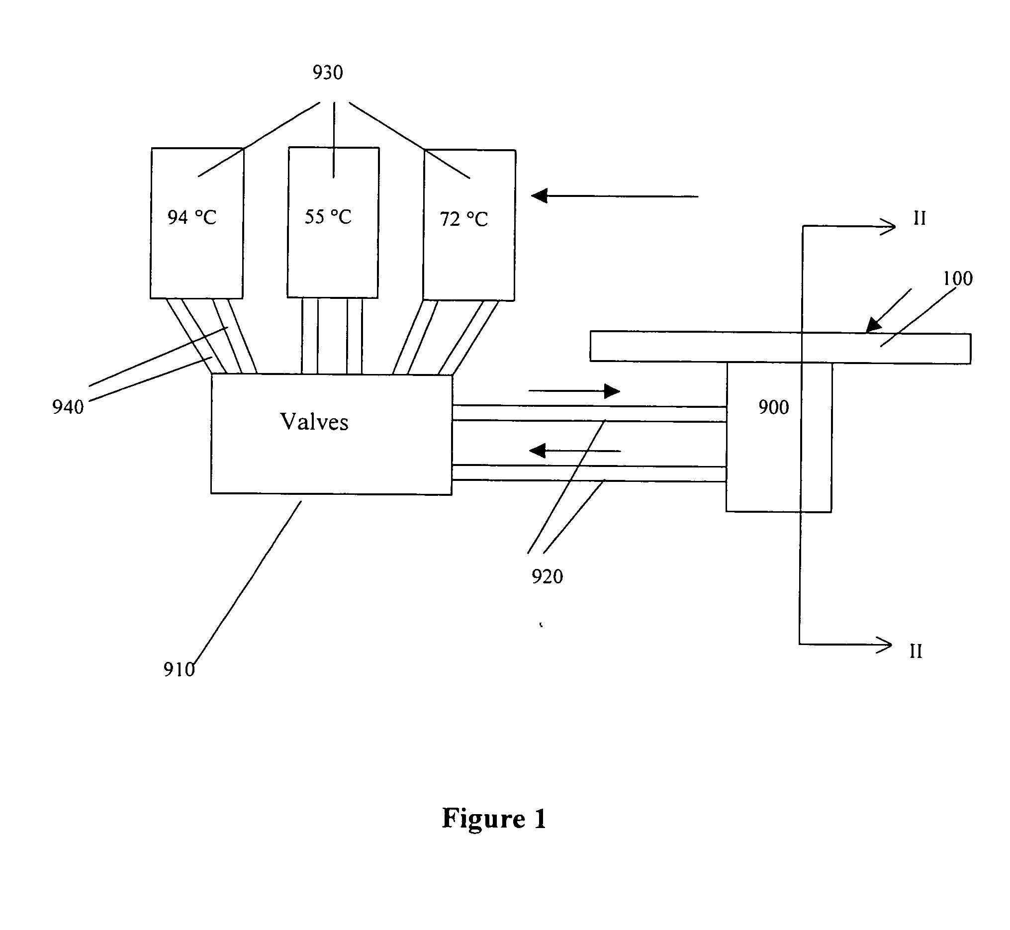
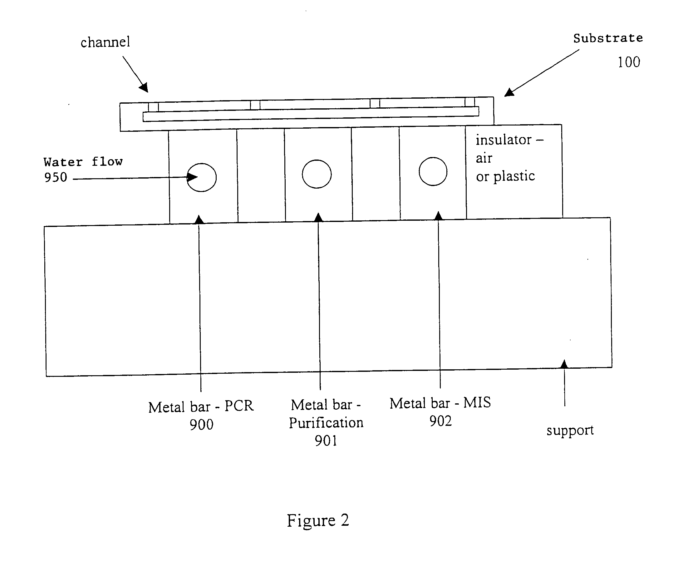
[0346] In one embodiment, the reaction mixture runs through a channel in which all the steps required for a genotyping protocol are performed: PCR, purification, microsequencing reaction and detection.

[0347] The microfluidic substrate comprises 100 channels in parallel. These channels are rectilinear and have a diameter of the order of 600 μm in the reaction zones. The surface area of the section of a channel is of the order of 0.25 mm2.

[0348] The genotyping protocol is carried out in parallel in the 100 channels. 100 samples are injected in parallel into the channels, and 100 such injections of sample are carried out sequentially, so that each channel contains 100 injections of the same sample. The microfluidic substrate thus makes it possible, by means of a cross-distribution of 100 samples for 100 polymorphisms, to carry out 10,000 genotyping reactions on a microfluidic substrate.

[0349] The injection...

example 3

Genotying by the Method of Allele-Specific Ligase Chain Reaction (LCR)

[0366] Allele-specific LCR, as disclosed in Barany et al. (PCR Meth. Appl. 1: 5-16 (1991), the contents of which are incorporated herein by reference in its entirety), employs four oligonucleotides two of which hybridize to one strand of target DNA and a complementary set of adjacent oligonucleotides, which hybridize to the opposite strand. Thermostable DNA ligase will covalently link each set, provided there is complete complementarity at the junction. A single-base mismatch at the oligonucleotide junction will not be amplified and is therefore distinguished; a second set of mutant-specific oligonucleotides is used in a separate reaction to detect or confirm the mutant allele(s).

[0367] A homogeneous phase protocol for allele-specific LCR can be carried out in accordance with the present invention by introducing into each channel 10 μl of starting mixture comprising: the DNA with the target sequence to be analyz...


PUM

PropertyMeasurementUnit
volumesaaaaaaaaaa
volumesaaaaaaaaaa
volumeaaaaaaaaaa

Abstract

Provided is a microfluidic device comprising a microfluidic substrate comprising at least one pathway for sample flow; and at least one thermal transfer member which is capable of cycling between at least two temperatures. The thermal transfer member is adapted to heat at least a portion of the sample pathway while a sample is flowing along said at least a portion of said sample pathway. Provided also are methods of carrying out biochemical protocols using such a device.

Description

RELATED APPLICATIONS [0001] The present application is a continuation of U.S. application Ser. No. 09 / 627,647, filed Jul. 28, 2000, which claims priority to French patent application serial No. 99 / 09806, filed Jul. 28, 1999; French patent application serial No. 99 / 11652, filed Sep. 17, 1999; and French patent application serial No. 99 / 12317, filed Oct. 1, 1999, the disclosures of all of which are incorporated herein by reference in their entireties.BACKGROUND [0002] Microfluidics consist of using microchannels instead of test tubes or microplates to carry out analyses and reactions. These microchannels or microcircuits are etches into silicon, quartz, glass, ceramics or plastic. The size of these channels is on the order of micrometers, while the reaction volumes are on the order of nonoliters or microliters. The principle of a microfluidic device is to guide reaction media containing reagents and samples, over zones which correspond to the different steps of the protocol. The integ...

Claims


Application Information

Patent Timeline
Patent Type & Authority Applications(United States)
IPC IPC(8): C07K1/26G01N33/53B01L3/00B01L7/00B01L7/02B81B1/00B81C1/00C12M1/00C12N15/09C12Q1/68G01N35/08G01N37/00
CPCB01L3/5025G01N35/08B01L7/02B01L7/52B01L7/525B01L7/5255B01L2200/0673B01L2200/10B01L2300/0816B01L2300/0845B01L2300/0867B01L2300/087B01L2300/1805B01L2300/1822B01L2300/1827B01L2300/1838B01L2300/1883B01L2400/0418B01L2400/0421B01L2400/0487F28F2260/02B01L3/5027
Inventor FOUILLET, YVESVAUCHIER, CLAUDECLERC, JEAN-FREDERICPEPONNET, CHRISTINE
Owner COMMISSARIAT A LENERGIE ATOMIQUE ET AUX ENERGIES ALTERNATIVES
Learn More