Heavy oil reforming method, an apparatus therefor, and gas turbine power generation system

a technology of heavy oil and gas turbines, which is applied in the direction of machines/engines, bulk chemical production, supercritical condition processes, etc., can solve the problem of not being able to make all the hydrocarbons in a heavy oil applicable as fuel, and achieve the effects of preventing corrosion of plant equipment, accelerating reaction, and accelerating carbon chain cleavag

Inactive Publication Date: 2006-01-19
HOKARI NOBUYUKI +4
View PDF14 Cites 88 Cited by
  • Summary
  • Abstract
  • Description
  • Claims
  • Application Information

AI Technical Summary

Benefits of technology

[0004] The purpose of the invention is to provide a heavy oil reforming method which reforms a heavy oil to give a fuel suitable for a gas turbine, eliminates sulfur and / or vanadium, which are the harmful components, from a heavy oil, and enables almost all the hydrocarbons in the heavy oil to be used in gas turbine combustion: an apparatus therefor; and a gas turbine power generation system using the reformed heavy oil as fuel.
[0023] As described above, the substances to be removed, such as sulfur and / or vanadium, can be eliminated from a heavy oil by an action of supercritical water as a solvent and an action of a hydrolyzing agent, and the eliminated substances are scavenged by a scavenger, so that the whole of the hydrocarbons in a heavy oil can be converted to a fuel for a gas turbine and can be burned. This enables use of low-cost heavy oils as a fuel for gas turbines, which leads to a reduction of a running cost and cuts down the equipment cost for the environmental apparatus and measures against corrosion of the gas turbines. Further, this realizes a reduction of environmental equipment cost and enables a continuous operation of the apparatus because of no ash deposition and a prevention of corrosion to attain a significant enhancement of the plant operating efficiency.

Problems solved by technology

The method of generating a gas from a heavy oil with supercritical water, as stated above, is capable of reforming part of a heavy oil to provide a fuel suited for a gas turbine, but incapable of making all the hydrocarbons in a heavy oil applicable as fuel.
Also, since the harmful components are concentrated in the residue, enlargement of the environmental protection equipment and measures against corrosion are required on the part of the boilers used for burning such oil.

Method used


Image

  • Heavy oil reforming method, an apparatus therefor, and gas turbine power generation system
  • Heavy oil reforming method, an apparatus therefor, and gas turbine power generation system
  • Heavy oil reforming method, an apparatus therefor, and gas turbine power generation system

Examples


example 1

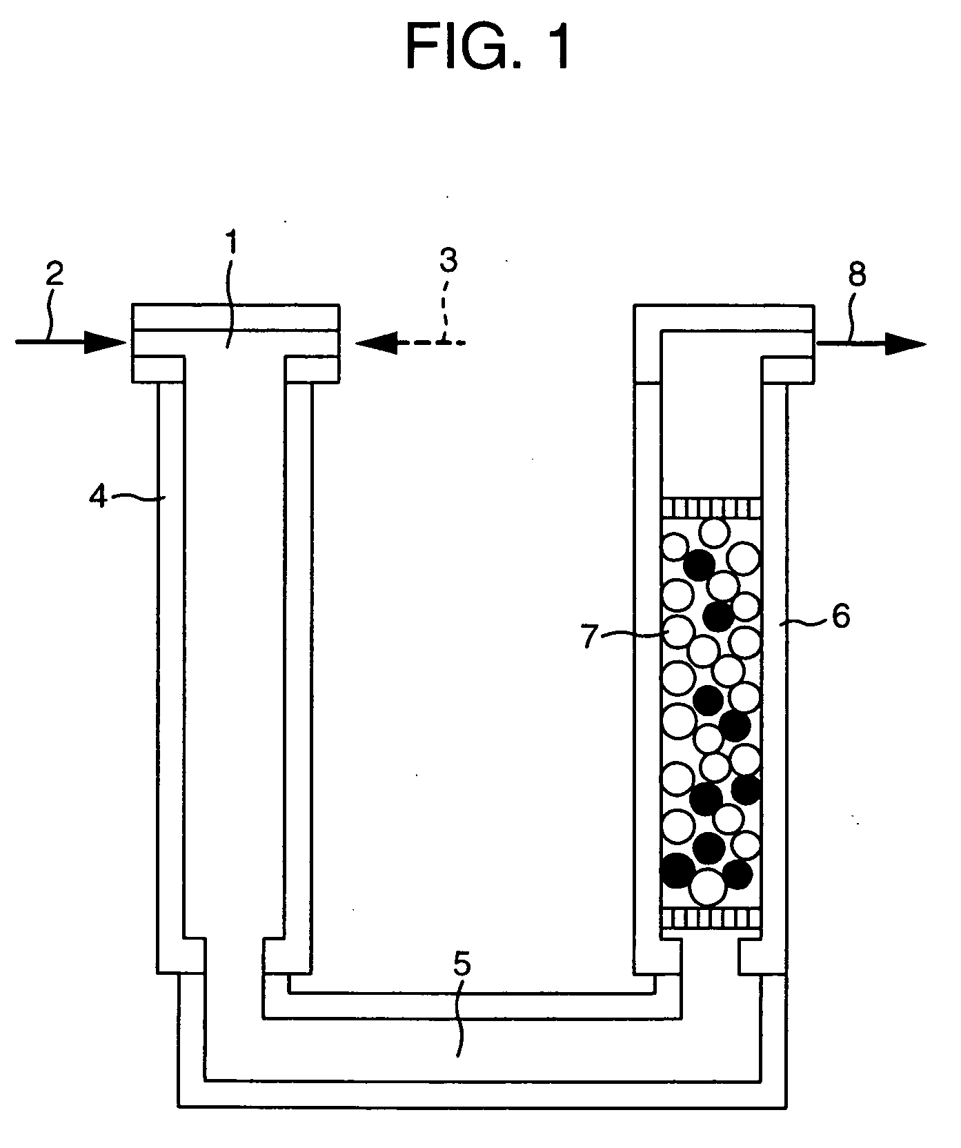
[0031]FIG. 1 is a schematic sectional view of the primary portion of the heavy oil reforming apparatus according to the present invention. At the inlet of the apparatus is provided a mixer 1 designed to receive and mix high-temperature and high-pressure water such as supercritical water 2 and a heavy oil 3. This water and heavy oil are mixed by the solvent action of the supercritical water in mixer 1, and the mixed liquid is led into a reactor 4. Mixing of supercritical water 2 and heavy oil 3 may be effected not only by simple joining of both fluids but can be also effected by forming a whirling flow or by making use of impingement of the counter flows of the two fluids for accelerating mixture.

[0032] Mixer 1 may not be provided, and super-critical water 2 and heavy oil 3 may be directly supplied into reactor 4. In reactor 4, there proceeds a reaction for eliminating from the hydrocarbon compounds the harmful components, i.e. sulfur and / or vanadium in the heavy oil under the actio...

example 2

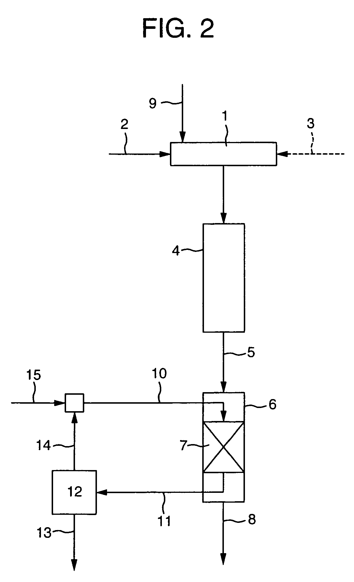
[0037]FIG. 2 is a block diagram showing the layout of the heavy oil reforming apparatus according to the present invention. In this example, a reaction assistant 9 which functions to accelerate the harmful component elimination reaction in reactor 4 is applied in addition to supercritical water 2 and heavy oil 3 in mixer 1. Reaction assistant 9 is a material selected from alkali metal or alkaline earth metal which acts to eliminate sulfur, a harmful component, in the form of a sulfate, hydrogen peroxide solution which accelerates the hydrolytic reaction, nitrate, formic acid and the like, or a mixture of such materials.

[0038] Addition of such a reaction assistant 9 is intended to elevate the harmful component elimination efficiency in reactor 4. As mentioned in Example 1, supercritical water 2, heavy oil 3 and reaction assistant 9 may be directly supplied to and mixed in reactor 4 without providing a mixer. Also, reaction assistant 9 may be either mixed in the system or may be prev...

example 3

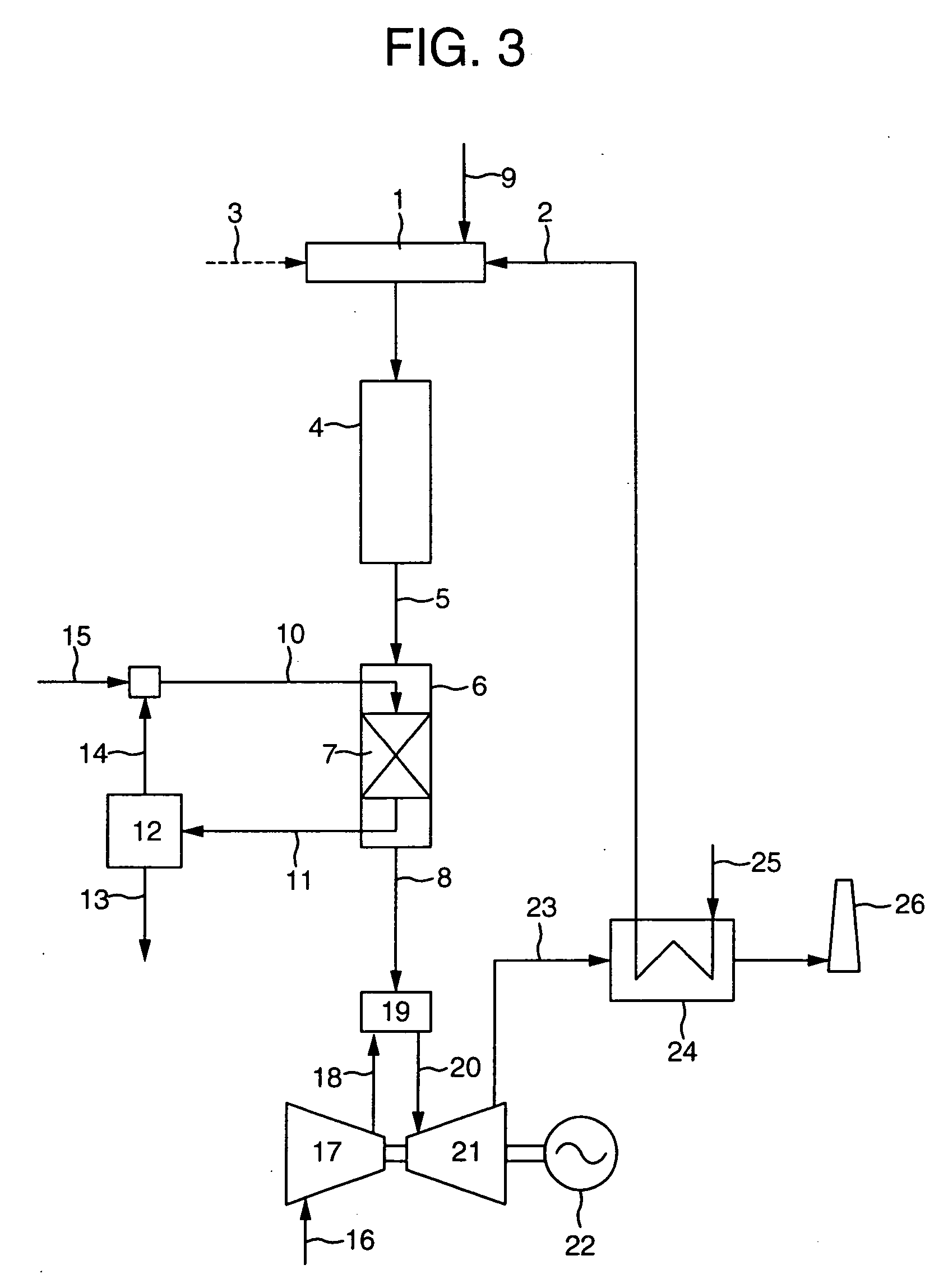
[0041]FIG. 3 is a block diagram showing an example of the gas turbine power generation system using the heavy oil reforming apparatus according to the present invention. In Examples 1 and 2, the reformed fuel 8 may be kept in storage or transported for use in a power plant, but in the instant example, the reformed fuel is immediately burned by a burner in the power generation system. Like in Example 2, a reaction accelerator 9 which accelerates the target substance elimination reaction in reactor 4 is mixed in addition to supercritical water 2 and heavy oil 3 in mixer 1.

[0042] Reaction accelerator 9 is a material selected from alkali metal or alkaline earth metal which eliminates sulfur, which is a substance to be removed, in the form of a sulfate, hydrogen peroxide solution which accelerates the hydrolytic reaction, and other materials such as nitrate and formic acid, or a mixture of such materials. The substances to be removed are eliminated from oil in reactor 4 and scavenged by...


PUM

PropertyMeasurementUnit
pressureaaaaaaaaaa
pressureaaaaaaaaaa
temperatureaaaaaaaaaa

Abstract

The purpose of the invention is to provide a heavy oil reforming method which reforms a heavy oil to give a fuel suitable for a gas turbine, eliminates sulfur and vanadium, i.e., harmful components, from a heavy oil, and enables almost all the hydrocarbons in the heavy oil to be used in gas turbine combustion; an apparatus therefor; and a gas turbine power generation system using the reformed heavy oil as fuel. This method comprises reacting a heavy oil with supercritical water and then with a scavenger for sulfur and vanadium to eliminate sulfur and vanadium from the heavy oil. The apparatus for reforming a heavy oil is equipped with a reactor for reacting a heavy oil with supercritical water, a scavenging apparatus filled with a scavenger for scavenging sulfur and vanadium in the heavy oil, and a connecting pipe for connecting the reactor and the scavenging apparatus. The gas turbine power generation system has a burner for burning a heavy oil reformed with the reforming apparatus and a gas turbine driven by a combustion gas generated by the burner.

Description

FIELD OF THE INVENTION [0001] The present invention relates to a heavy oil reforming method, an apparatus therefor, and a gas turbine power generation system using the reformed heavy oil as fuel. BACKGROUND OF THE INVENTION [0002] Various techniques for reforming heavy oils for use as fuel for the gas turbines have been proposed. There are known, for instance, a method in which the hydrocarbons in a heavy oil are decomposed with supercritical water to convert the heavy oil to a lighter type and a combustible gas is produced therefrom (JP-A-11-246876), and a proposal in which the produced gas is burned to drive a gas turbine while the residue left after oil conversion to a lighter type is burned by a boiler, using the generated heat for producing electric power by a steam turbine (JP-A-11-80750). These techniques may be boiled down to an idea of taking out part of the hydrocarbons in a heavy oil to concentrate the harmful components in the residue. SUMMARY OF THE INVENTION [0003] The...

Claims


Application Information

Patent Timeline
Patent Type & Authority Applications(United States)
IPC IPC(8): C10G9/00C10G45/00B01J10/00B01J8/04B01J3/00B01J8/00B01J8/02B01J8/06C01B3/34C01B3/36C01G31/02F02C3/20
CPCB01J3/008B01J8/0055B01J8/025B01J8/065B01J2219/00006F02C3/20C01B3/36C01B2203/0216C01B2203/0255C01B2203/1247C01G31/02C01B3/34Y02P20/129Y02P20/54
Inventor HOKARI, NOBUYUKIMIYAMOTO, TOMOHIKOTAKAHASHI, HIROKAZUMORIHARA, ATSUSHIKOIZUMI, HIROMI
Owner HOKARI NOBUYUKI
Why Eureka
Try Eureka