Engine control circuit device

a technology of control circuit and engine, which is applied in the direction of printed circuit aspects, electrical apparatus construction details, electrical apparatus casings/cabinets/drawers, etc., can solve the problems of increasing the cost, affecting and affecting the operation of the engine. , to achieve the effect of increasing the heat resistance of the engine control circuit devi

Inactive Publication Date: 2006-01-19
HITACHI LTD
View PDF36 Cites 87 Cited by
  • Summary
  • Abstract
  • Description
  • Claims
  • Application Information

AI Technical Summary

Benefits of technology

[0022] According to the present invention, it is possible to increase heat resistance of the engine

Problems solved by technology

However, the related art has the following problem.
In the disclosed electronic circuit device, though not clearly stated in Patent Reference 1, the resin filled between the metal substrate and the case is presumably a thermoplastic resin (for the reason that, if a thermo-setting resin is filled, the resin must

Method used


Image

  • Engine control circuit device
  • Engine control circuit device
  • Engine control circuit device

Examples


first embodiment

[0047] the present invention will be described with reference to FIGS. 1 and 2.

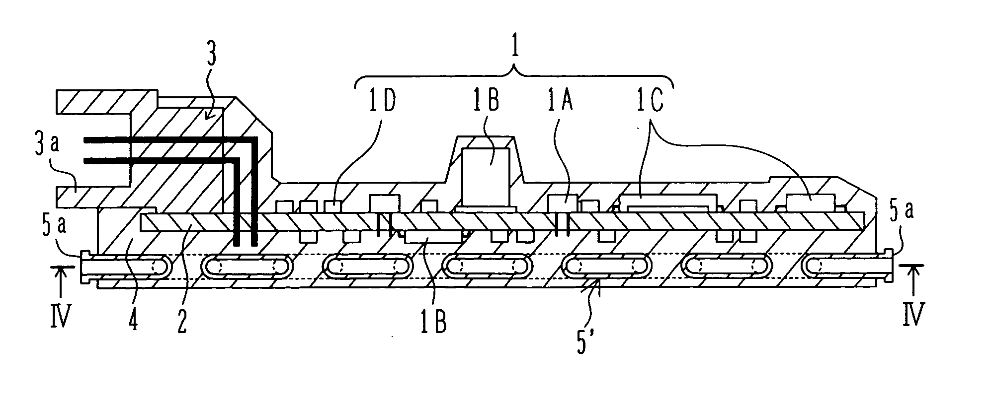
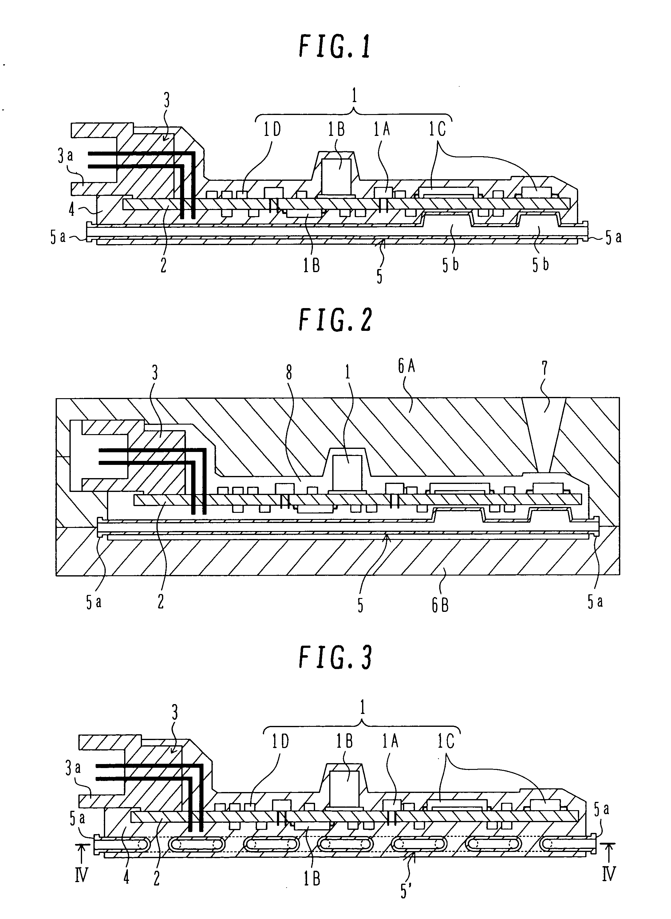
[0048]FIG. 1 is a vertical sectional view showing an overall structure of an engine control circuit device according to the first embodiment of the present invention.

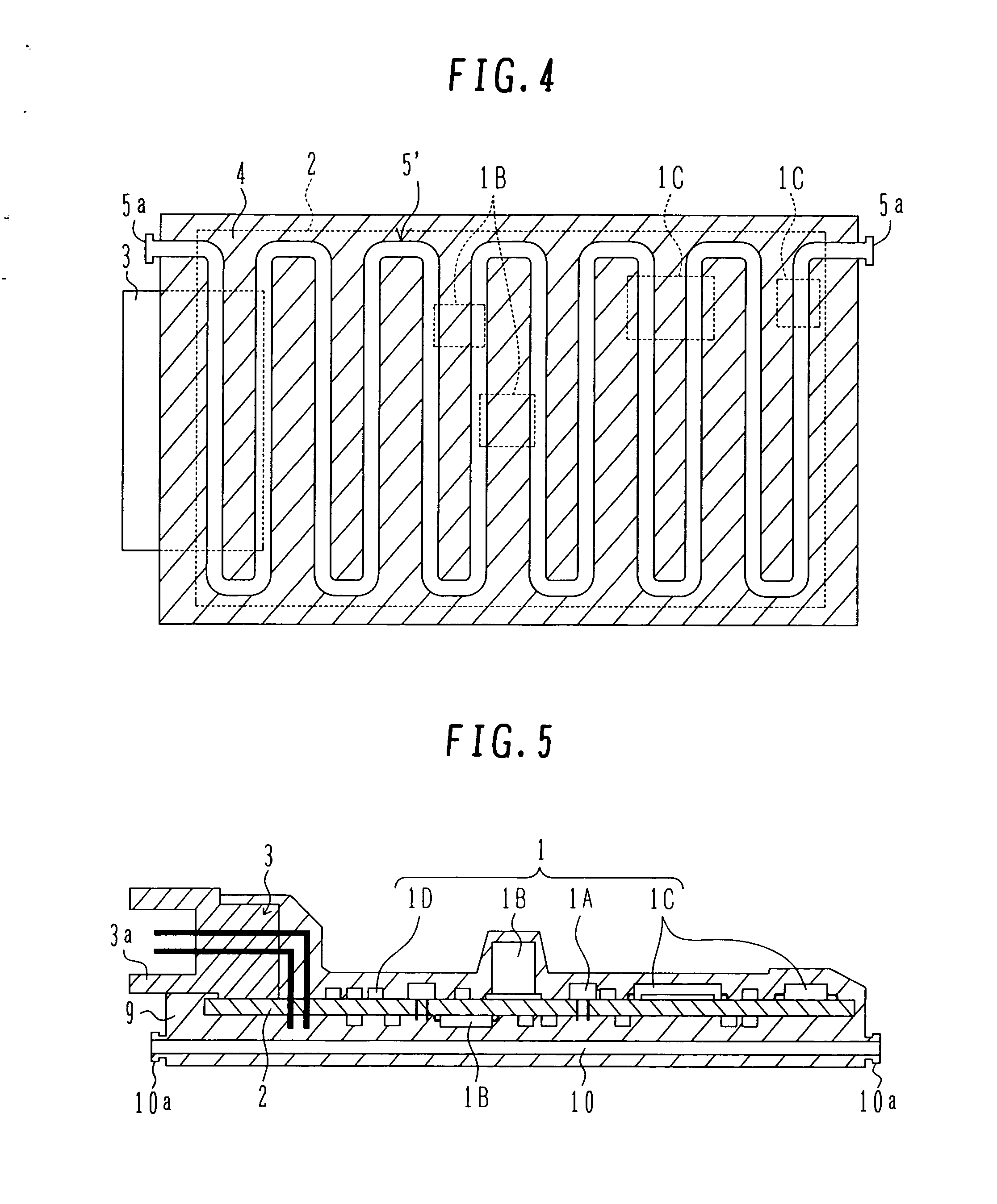
[0049] In FIG. 1, the engine control circuit device comprises a circuit board 2 including a plurality of packaged electronic parts 1 mounted on, e.g., both surfaces thereof, a connector 3 for connection to an external circuit (not shown), a resin portion 4 formed of a thermo-setting resin and covering the connector 3 except for a connecting portion 3a thereof and the entirety of the circuit board 2, and a cooling pipe 5 (cooling means) disposed below the circuit board 2 (on the lower side as viewed in FIG. 1) and integrally molded in the resin portion 4. A coolant flows through the cooling pipe 5 to cool the resin portion 4.

[0050] The electronic parts 1 include, for example, board-inserted electronic parts 1A (such as a resistor, a capacito...


PUM


Abstract

An engine control circuit device which has higher heat resistance and can be installed in a place exposed to severe thermal environments. In an engine control circuit device comprising a circuit board on which a plurality of packaged electronic parts are mounted, and a connector mounted on the circuit board for connection to an external circuit, the device further comprises a resin portion formed of a thermo-setting resin and covering the connector except for a connecting portion thereof and the circuit board, and a cooling pipe integrally molded in the resin portion and allowing a coolant to flow through it, thereby cooling the resin portion.

Description

BACKGROUND OF THE INVENTION [0001] 1. Field of the Invention [0002] The present invention relates to a circuit device comprising a circuit board on which a plurality of packaged electronic parts are mounted, and a connector mounted on the circuit board for connection to an external circuit. More particularly, the present invention relates to an engine control circuit device for use in automobiles, ships, agricultural machines, engineering machines, and so on. [0003] 2. Description of the Related Art [0004] Recently, thermal environments of a module for controlling engines used in automobiles, ships, agricultural machines, engineering machines, etc. (hereinafter such a module is referred to as an “engine control circuit device”) have become increasingly severe year by year. In other words, the installation place of the engine control circuit device has changed from a compartment to an engine room and then to a location on an engine itself (called “on-engine mounting”). Correspondingl...

Claims


Application Information

Patent Timeline
IPC IPC(8): H01L23/34
CPCH05K1/0203H05K1/0272H05K1/189H05K2203/1316H05K7/20872H05K2201/064H05K2201/066H05K3/284H05K5/0034
Inventor KADOYA, KIYOOMIEGUCHI, SHUUJISASAKI, MASAHIROMAYUZUMI, TAKUYA
Owner HITACHI LTD
Why Eureka
Try Eureka