Method of manufacturing a metal-reinforced plastic panel
Inactive Publication Date: 2006-01-19
CRANE BUILDING PRODS
View PDF98 Cites 18 Cited by
Summary
Abstract
Description
Claims
Application Information
AI Technical Summary
This helps you quickly interpret patents by identifying the three key elements:
Problems solved by technology
Method used
Benefits of technology
[0013] The present invention also describes a top cap that may be used in conjunction with a composite panel as described as an exemplary embodiment above to make a new system of constructing seawalls or anchored sheet pile walls. The top cap takes advantage of the inherent structural strength of steel and the corrosion resistance of plastic in its form as an essentially U-shaped member made from at least one sheet of metal substrate that has a coextruded plastic covering on some or all sides of the substrate. The top cap may serve as the cover for the upper end of a seawall and the connection point for a tie rod that is in turn connected to an anchor point. The new system of seawall construction takes advantage of the inherent strength of the metal substrate, such as steel, that would comprise an example embodiment of the wall panel. The new wall system allows an anchored seawall to derive its anchoring support from a plurality of anchors and tie rods connected to the seawall panels solely at the upper end of the panels where the top cap has been placed to c
Problems solved by technology
Over the years, there has existed the problem of land erosion caused by waterways such as rivers, streams, ponds, lakes, seas, and oceans.
The seawall panels may be subjected to enormous pressures and loads which, if forceful enough, may ultimately break the connection between adjacent seawall panels.
Consequently, the barrier may become less effective over time, and individual seawall panels may have to be repaired or replaced.
This may be expensive, and it may require the use of special heavy construction equipment.
In addition, water loads on the wall include hydrostatic pressure due to a difference in water level
Method used
Image
Click on the blue label to locate the original text in one second.
Reading with bidirectional positioning of images and text.
Examples
Embodiment Construction
)
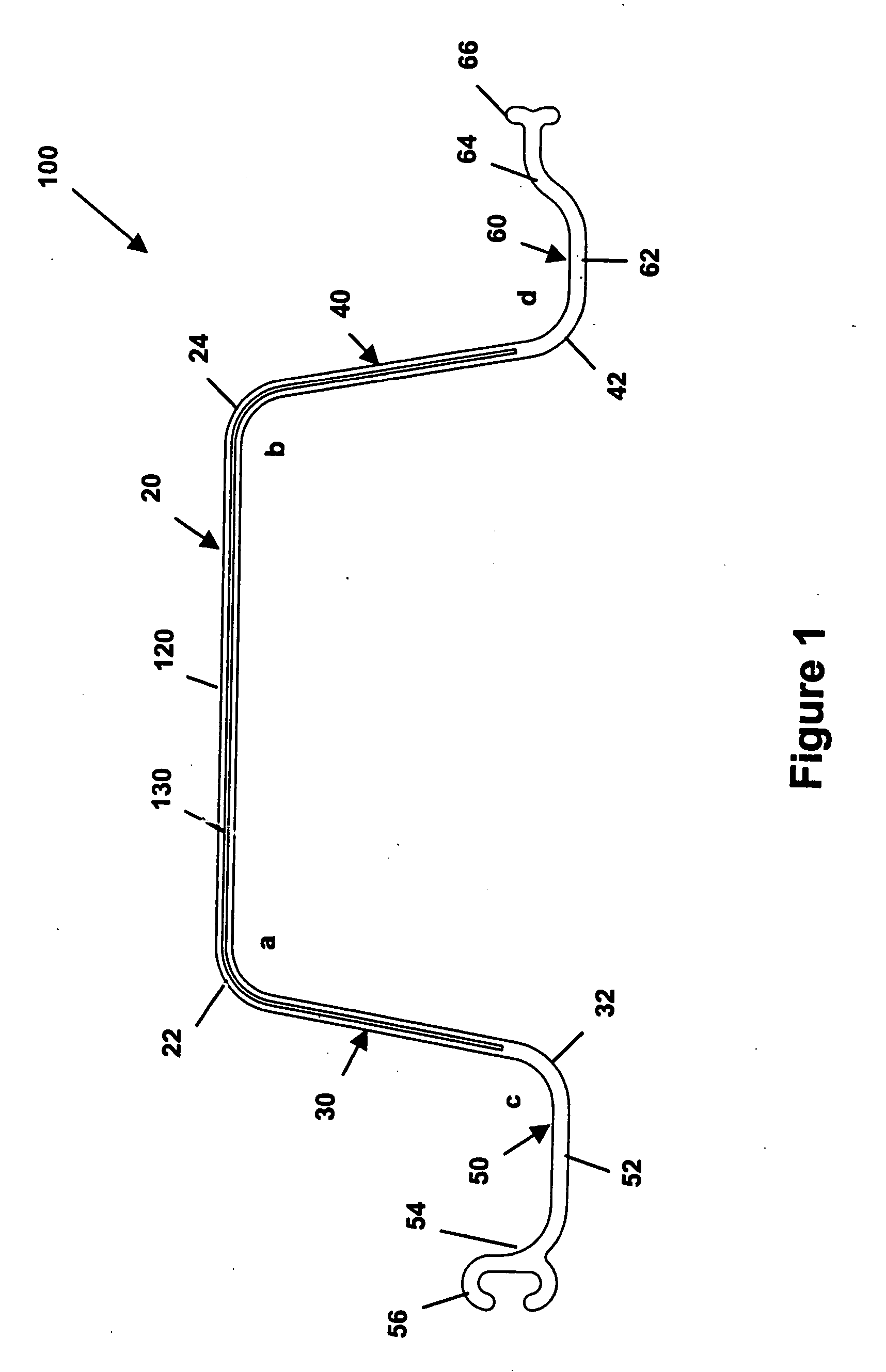
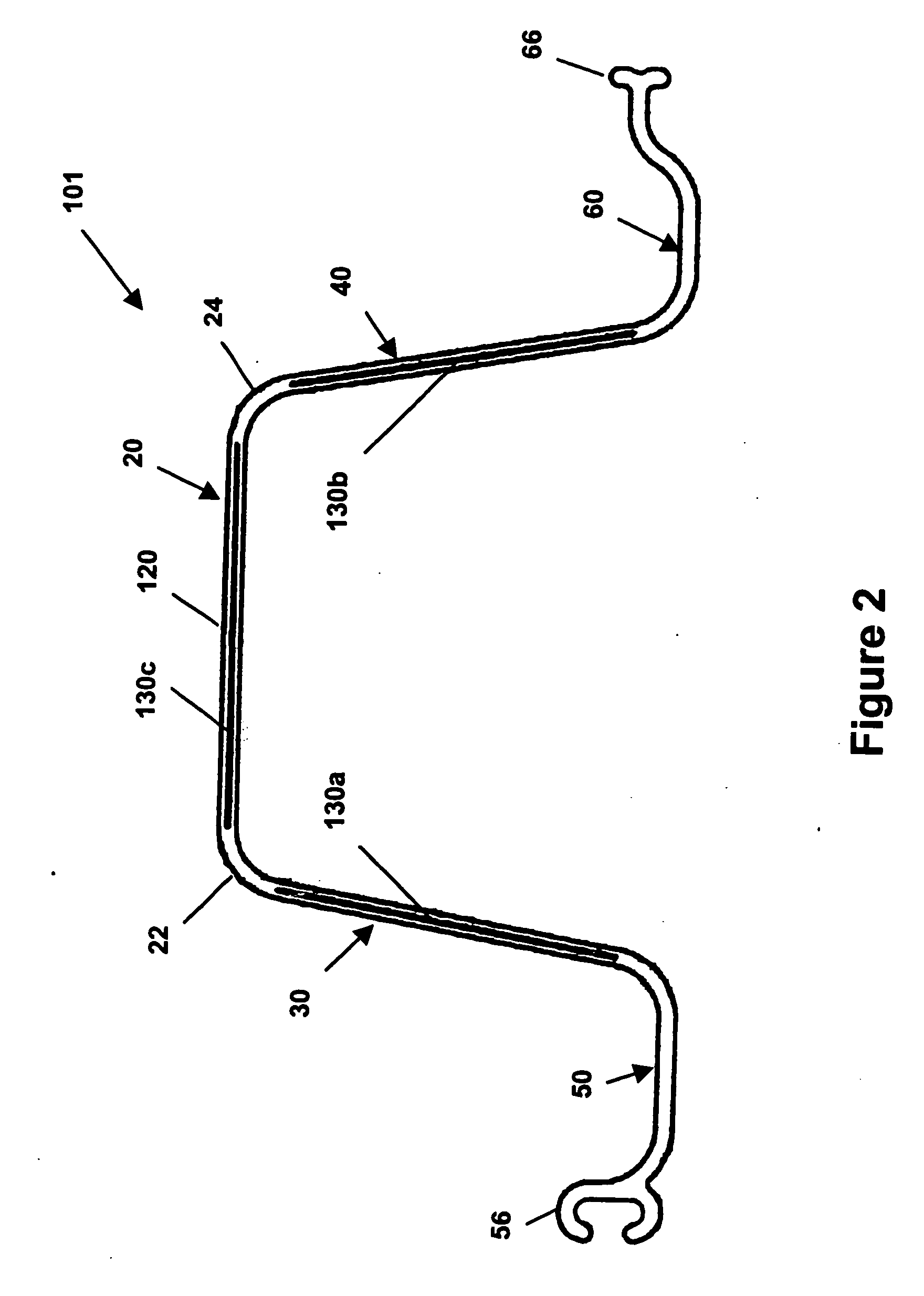
[0034] The present invention is directed to a retaining panel that may protect against a bounding shore with its top preferably extending above ground level and its bottom preferably anchored down into the ground below the water bottom. FIGS. 1 and 2 illustrate cross-sectional views of two exemplary embodiments of a retaining panel of the present invention. FIGS. 6 through 11 illustrate various perspective, plan, and elevational views of the exemplary embodiments shown in FIGS. 1 and 2. The retaining panel 100 includes a sheet of metal substrate 130, a coextruded layer of plastic 120, a central portion 20, a first side portion 30, a second side portion 40, a first flange 50, and a second flange 60. As shown in these figures, the retaining panel 100 is preferably of one-piece construction for maximum durability and longevity. A one-piece construction preferably eliminates unnecessary joints which may eventually fail under the pressures and loads in the field. In fact, the inventors ...
PUM
Property
Measurement
Unit
Width
aaaaa
aaaaa
Width
aaaaa
aaaaa
Shape
aaaaa
aaaaa
Abstract
A composite panel comprised of a sheet of substrate and a coextruded layer of plastic covering the substrate. The panel may be used as a retaining panel for a body of water in a cantilever wall or an anchored sheet pile wall. The retaining panel may include a central portion, two side portions, and two flanges. The retaining panel may also include integral connecting portions. The substrate may be comprised of a material such as aluminum or steel, while the plastic may be a material such as polyvinyl chloride (PVC). Other applications of the composite panel include uses as building panels for sidewalls or roofs.
Description
[0001] This application is a continuation of U.S. application Ser. No. 10 / 452,612, filed Jun. 2, 2003, which claims the benefit of U.S. Provisional Application No. 60 / 385,430, filed May 31, 2002, and U.S. Provisional Application No. 60 / 450,415, filed Feb. 27, 2003, each of which is hereby incorporated by reference in its entirety.BACKGROUND AND SUMMARY OF THE INVENTION [0002] The present invention relates generally to a retaining panel for a body of water and, more particularly, to a retaining panel that may protect against a bounding shore with its top preferably extending above ground level and its bottom preferably anchored down into the ground below the water bottom. An exemplary embodiment of a retaining panel of the present invention may be adapted for use as a seawall, a ground erosion barrier, a barrier against land erosion caused by waterways such as rivers, streams, ponds, lakes, seas, and oceans, a shoreline bulkhead, a wave breaker, a retaining wall, a footbridge, or as ...
Claims
Application Information
Patent Timeline
Application Date:The date an application was filed.
Publication Date:The date a patent or application was officially published.
First Publication Date:The earliest publication date of a patent with the same application number.
Issue Date:Publication date of the patent grant document.
PCT Entry Date:The Entry date of PCT National Phase.
Estimated Expiry Date:The statutory expiry date of a patent right according to the Patent Law, and it is the longest term of protection that the patent right can achieve without the termination of the patent right due to other reasons(Term extension factor has been taken into account ).
Invalid Date:Actual expiry date is based on effective date or publication date of legal transaction data of invalid patent.