Phase shift modulation-based control of amplitude of AC voltage output produced by double-ended DC-AC converter circuitry for powering high voltage load such as cold cathode fluorescent lamp

a technology of phase shift modulation and control of amplitude, applied in the direction of dc-ac conversion without reversal, process and machine control, instruments, etc., can solve the problems of inconvenient operation, high cost, and undesirable effects

Inactive Publication Date: 2006-01-19
INTERSIL INC
View PDF37 Cites 31 Cited by
  • Summary
  • Abstract
  • Description
  • Claims
  • Application Information

AI Technical Summary

Benefits of technology

[0007] In accordance with the present invention, disadvantages, such as those described above, of conventional high voltage AC power supply system architectures, including systems for supplying AC power to CCFLs used to back-light an LCD panel, are effectively obviated by a double-ended, DC-AC converter architecture, which is operative to drive opposite ends of a load, such as a CCFL, with a first and second sinusoidal voltages having the same frequency and amplitude, but having a controlled phase difference therebetween. By controlling the phase difference between the first and second sinusoidal voltages, the present invention is able to vary the amplitude of the composite voltage differential produced across the opposite ends of the load.
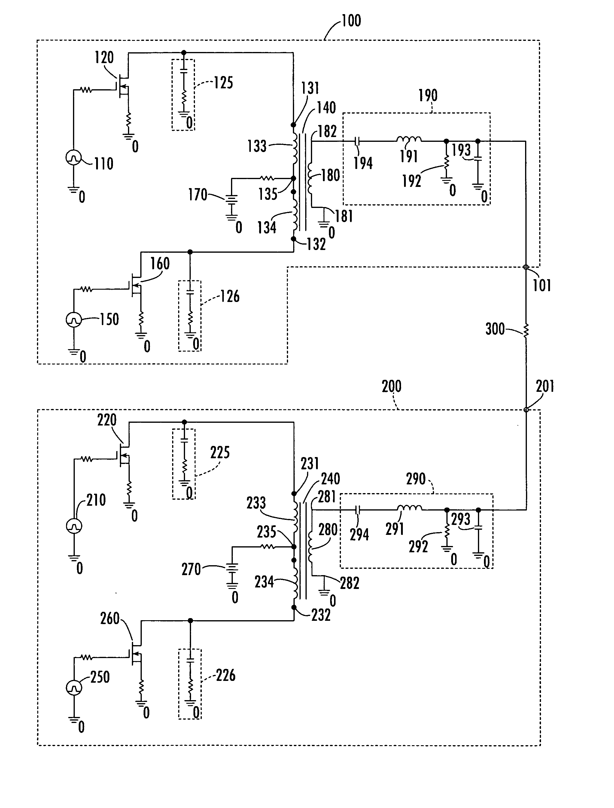
[0009] The operation of a respective push-pull DC-AC converter stage is as follows. The complementary phase, rectangular waveform, 50% duty cycle output pulse trains produced by the two pulse generators will alternately turn the two MOSFETs on and off, in a mutually complementary manner, such that, as one MOSFET is turned on, the other MOSFET will be turned off, and vice versa. Whichever MOSFET is turned on will provide a current flow path to ground from the voltage source feed through half of the center tapped primary winding and the drain-source path of that MOSFET. The alternating of the conduction cycles of the two MOSFETs of a respective converter stage has the effect of producing a generally rectangular output pulse waveform having a 50% duty cycle across the secondary winding of the step-up transformer for that stage. The amplitude of this voltage waveform corresponds to the product of the secondary:primary turns ratio of the transformer and twice the value of the DC voltage of the voltage feed source. As pointed out above, the shape of this generally rectangular waveform is converted by the RLC filter into a relatively well defined sinusoidal waveform, that is supplied to one of the two output ports.
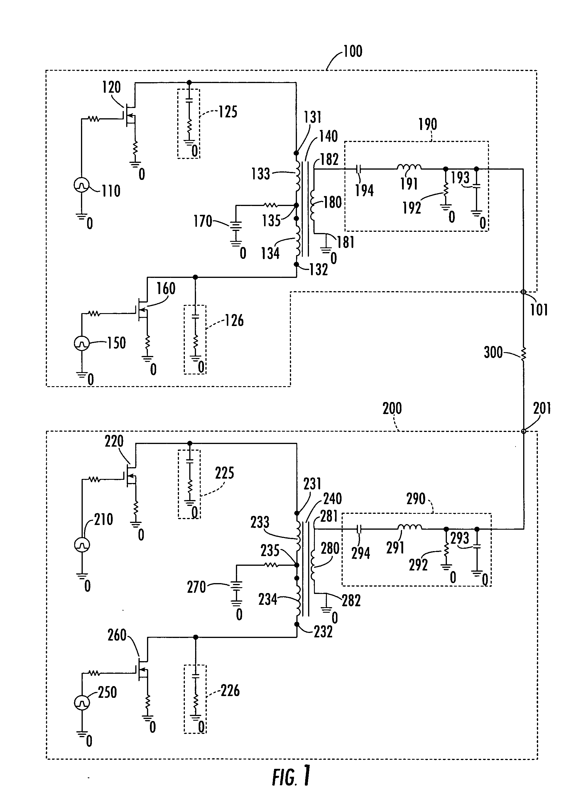
[0010] In accordance with the controlled phase shift mechanism of the present invention, the phase of the sinusoidal waveform produced by the output RLC filter of one of the converter stages is controllably shifted by a prescribed amount relative to the phase of the sinusoidal waveform produced by the output RLC filter of the other converter stage. This controlled imparting of a differential phase shift between the sinusoidal waveforms appearing at the two output ports has the effect of modifying the shape and thereby the amplitude of the composite AC signal produced between the two output ports.
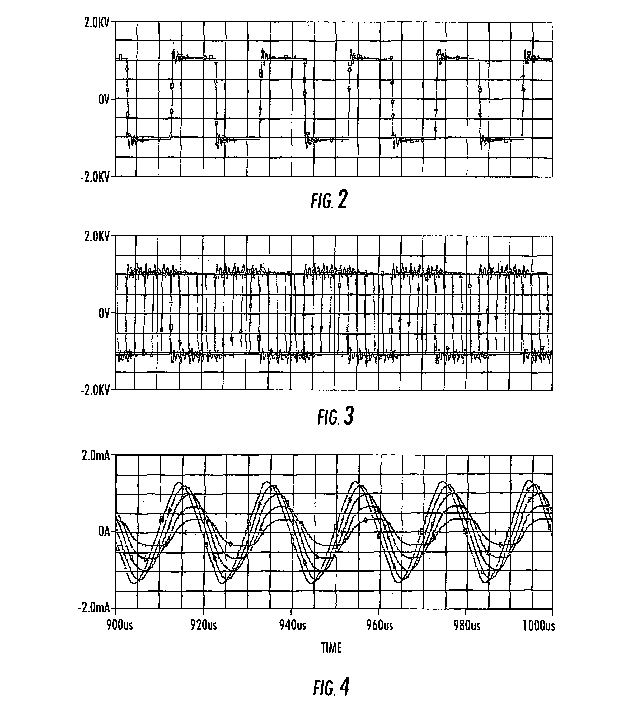
[0012] In accordance with a non-limiting, but preferred embodiment of the invention, producing the incremental phase offsets between the two waveforms generated by the two converter stages is readily accomplished by imparting a controlled amount of delay to the pulse trains produced by the pulse generators of one of the converter stages relative to the pulse trains produced by pulse generators of the other converter stage. The amount of delay between the two pulse trains will control the shape and thereby the amplitude of the composite AC waveform produced across the output ports.
[0017] In order to controllably shift the phase of the resultant sine wave supplied to the one output port relative to the other output port, transitions in the complementary 50% duty cycle pulse trains produced by the pulse generators of one converter stage are incrementally delayed with respect to the pulse trains produced by the pulse generators of the other stage, so as to controllably shift the phase of the sine wave supplied to the one output port relative to the other output port. As in the voltage-fed embodiment, incrementally offsetting in phase of the two sine waveforms produced by the push-pull DC-AC converter stages of the current-fed embodiment serves to vary or modulate the amplitude of the composite waveform produced across the two output terminals.
[0020] Incrementally varying the magnitude of the DC voltage applied to the voltage control input of the one-shot serves to controllably adjust the delay between the transitions in the complementary 50% duty cycle pulse trains produced by one pair of pulse generators with respect to the pulse trains produced by the other pair of pulse generators, so as to controllably shift the phase of the resultant sine wave supplied to one output port relative to the sine wave applied to the other output port. As described above, this serves to modulate the amplitude of the composite AC voltage produced across the opposite ends of the load.

Problems solved by technology

This technique is undesirable, as it involves the generation of a very high peak AC voltage in the high voltage transformer circuitry feeding the driven end of the lamp.
These wires can be relatively long (e.g., four feet or more), and are more expensive than low voltage wires; in addition, they lose substantial energy through capacitive coupling to ground.
This approach has disadvantages similar to the first, in that the gate (or base) drive wires are required to carry high peak currents and must change states at high switching speeds for efficient operation.
The long wires required are not readily suited for these switching speeds, due their inherent inductance; in addition they lose energy because of their substantial resistance.

Method used


Image

  • Phase shift modulation-based control of amplitude of AC voltage output produced by double-ended DC-AC converter circuitry for powering high voltage load such as cold cathode fluorescent lamp
  • Phase shift modulation-based control of amplitude of AC voltage output produced by double-ended DC-AC converter circuitry for powering high voltage load such as cold cathode fluorescent lamp
  • Phase shift modulation-based control of amplitude of AC voltage output produced by double-ended DC-AC converter circuitry for powering high voltage load such as cold cathode fluorescent lamp

Examples


Embodiment Construction

[0026] Before detailing the double-ended, phase modulation-based DC-AC converter architecture of the present invention, it should be observed that the invention resides primarily in a prescribed novel arrangement of conventional controlled power supply circuits and components. Consequently, the configurations of such circuits and components and the manner in which they may be interfaced with a driven load, such as a cold cathode fluorescent lamp have, for the most part, been shown in the drawings by readily understandable schematic block diagrams, and associated waveform diagrams, which show only those specific aspects that are pertinent to the present invention, so as not to obscure the disclosure with details which will be readily apparent to those skilled in the art having the benefit of the description herein. Thus, the schematic block diagrams are primarily intended to show the major components of various embodiments of the invention in convenient functional groupings, whereby ...


PUM


Abstract

A double-ended, DC-AC converter supplies AC power to a load, such as a cold cathode fluorescent lamp used to back-light a liquid crystal display. First and second converter stages generate respective first and second sinusoidal voltages having the same frequency and amplitude, but having a controlled phase difference therebetween. By employing a voltage controlled delay circuit to control the phase difference between the first and second sinusoidal voltages, the converter is able to vary the amplitude of the composite voltage differential produced across the opposite ends of the load. The converter may be either voltage fed or current fed.

Description

CROSS-REFERENCE TO RELATED APPLICATION [0001] [001]The present application claims the benefit of previously filed, co-pending U.S. Patent Application Ser. No. 60 / 589,172, filed Jul. 19, 2004, by R. Lyle et al, entitled: “Phase Shift Modulation for Double Ended, Push Pull Inverter,” assigned to the assignee of the present application and the disclosure of which is incorporated herein.FIELD OF THE INVENTION [0002] The present invention relates in general to power supply systems and subsystems thereof, and is particularly directed to a method and apparatus for controlling the amplitude of an AC voltage supplied to a high voltage device, such as a cold cathode fluorescent lamp of the type employed for back-lighting a liquid crystal display. BACKGROUND OF THE INVENTION [0003] There are a variety of electrical system applications which require one or more sources of high voltage AC power. As a non-limiting example, a liquid crystal display (LCD), such as that employed in desktop and lapto...

Claims


Application Information

Patent Timeline
Patent Type & Authority Applications(United States)
IPC IPC(8): H05B37/02
CPCH05B41/3927H05B41/2824H02M7/519H02M7/48
Inventor LYLE, ROBERT L. JR.LAUR, STEVEN P.MOUSSAOUI, ZAKI
Owner INTERSIL INC
Why Eureka
Try Eureka