Electric motor control strategies

a technology of electric motors and control strategies, applied in the direction of machines/engines, mechanical equipment, engine starters, etc., can solve the problems of unsatisfactory torque control, potential challenges, and difficulty in obtaining sufficient motor position information to provide accurate torque control

Active Publication Date: 2006-01-19
HAMILTON SUNDSTRAND CORP
View PDF10 Cites 26 Cited by
  • Summary
  • Abstract
  • Description
  • Claims
  • Application Information

AI Technical Summary

Benefits of technology

[0012] In another example, the controller determines when the motor is disengaged from the device for a period of time and changes a motor torque reference signal from a present signal value corresponding to a present, operating motor speed to a higher value. In one example, the controller increases the value of the motor torque reference signal to the maximum allowable for the particular motor.

Problems solved by technology

Regardless of the type of motor used, there are potential challenges during operation of the electric start system or the associated engine.
For example, during an initial start up it is difficult to obtain sufficient motor position information to provide accurate torque control.
Another potential challenge is to avoid undesirable disengagement between the motor and the associated engine.
Systems that have a clutch for purposefully disengaging the motor and the engine present the possibility for inadvertent or undesirable disengagement.
Another issue presented by typical electric start systems is that reengagement between the motor and engine may exceed the clutch rating or excite the engine dynamic system.
Another problem associated with inadvertent disengagement is that a gain of a motor speed control loop becomes significantly higher compared to the gain when the components are reengaged.
This condition may lead to underdamped or unstable speed loop operation during the period of disengagement, which is undesirable.
The limitation on such an arrangement is that if the acceleration rate is set too high it may overstress the motor drive because it will reach the current limit, for example.
If, on the other hand, the acceleration rate is set too low, it undesirably increases engine start time.
Moreover, with an electric engine start system having a clutch, a fast deceleration rate may lead to motor disengagement.

Method used


Image

  • Electric motor control strategies
  • Electric motor control strategies
  • Electric motor control strategies

Examples


Embodiment Construction

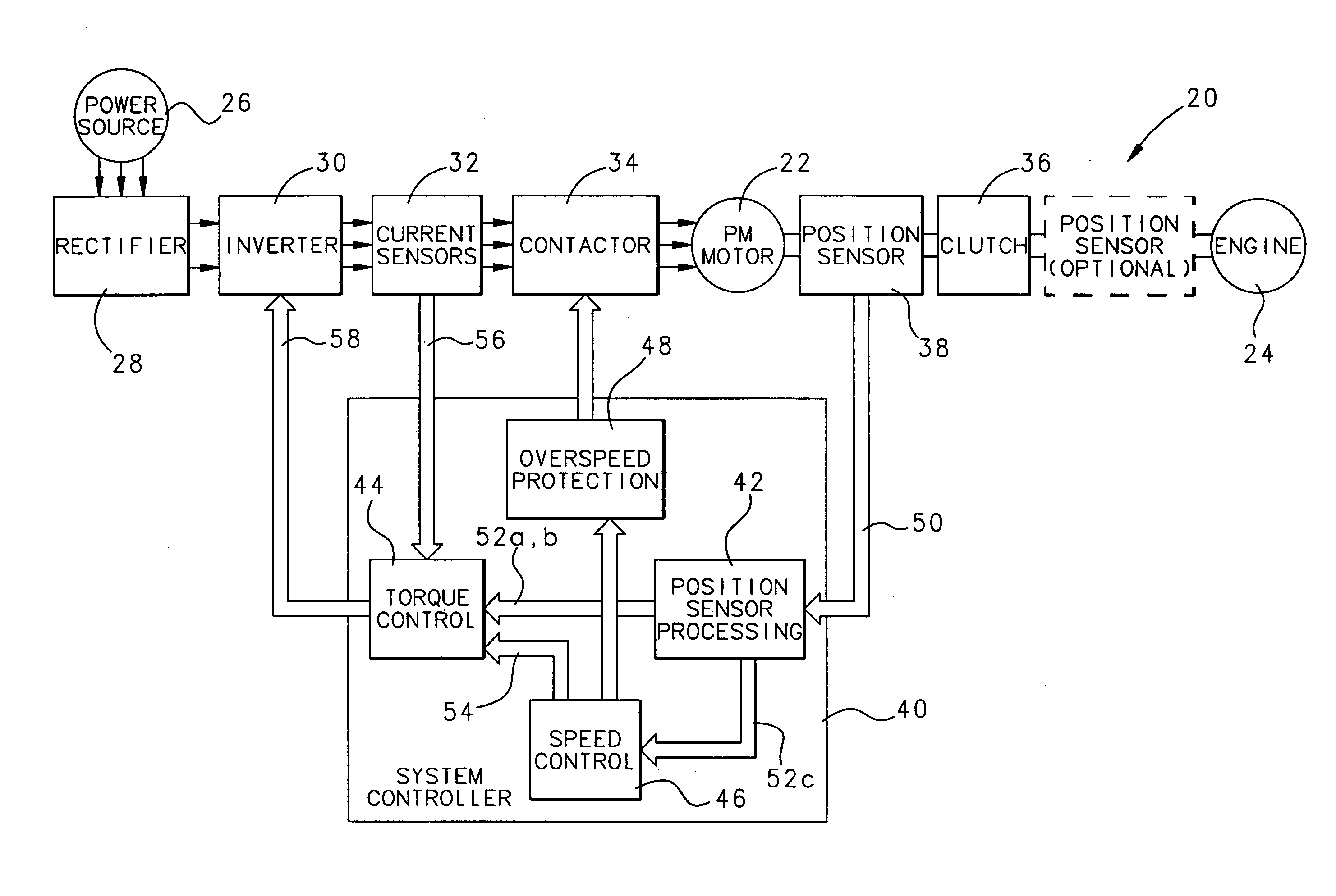
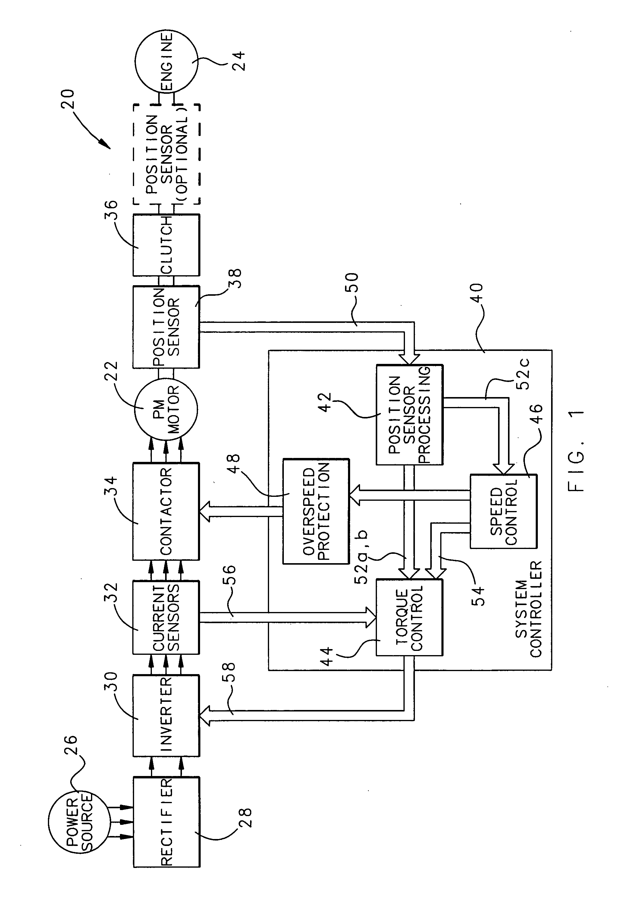
[0032]FIG. 1 schematically illustrates an electric start system 20 having an electric motor 22 for starting an engine 24. In one example, the motor 22 is a permanent magnet motor and the engine 24 is a gas turbine engine. The motor 22 receives power from a power source or grid 26 through a rectifier 28 that is in series with an inverter 30, both of which may operate in a known manner. Current sensors 32 and a contactor 34 are provided between the inverter 30 and the motor 22 for control and inverter protection, respectively. The current sensors 32 and contactor 34 operate in a known manner.

[0033] A low resolution position sensor 38 provides motor position information to a controller 40 that controls operation of the motor 22. In one example, the position sensor 38 comprises at least one hall sensor and provides output signals with a plurality of phases that equals the number of phases of the motor 22. In one example, the number of hall sensors equals the number of phases of the mot...


PUM


Abstract

An electric start system (20) includes a controller (40) that controls operation of a motor (22) used to start a device such as a gas turbine engine (24). In one example, the controller (40) determines when an acceleration rate of the motor (22) is outside of a desired range and dynamically controls the acceleration rate. In another example, the controller (40) determines when the motor (22) is disengaged from the engine (24) and controls a torque reference value to facilitate smoother reengagement. In another example, the controller (40) provides an initial starting torque value that allows for soft starting capabilities of the motor (22).

Description

1. FIELD OF THE INVENTION [0001] This invention generally relates to electric motor control. More particularly, this invention relates to electric motor control strategies useful for electric start systems. 2. DESCRIPTION OF THE RELATED ART [0002] Electric motors have a variety of uses. One is for electric start systems for starting engines, such as gas turbine engines. Different types of electric motors have been used for such purposes. In some instances, AC brushless motors with sinusoidal back-EMF and current wave forms are employed in electric engine start systems that require very smooth torque control. Such arrangements include a high number of poles to achieve higher power density (i.e., a higher ratio of torque per amp). [0003] Regardless of the type of motor used, there are potential challenges during operation of the electric start system or the associated engine. For example, during an initial start up it is difficult to obtain sufficient motor position information to pro...

Claims


Application Information

Patent Timeline
Patent Type & Authority Applications(United States)
IPC IPC(8): H02P7/00
CPCF02C7/275F02N11/0851F02N11/0859F02N2300/104F02N2200/041F02N2200/044F02N2300/102F02N2011/0896
Inventor ROZMAN, GREGORY I.MARKS, KENNETHGUSTAFSON, JAMES R.PARSONS, DOUGLAS
Owner HAMILTON SUNDSTRAND CORP
Why Eureka
Try Eureka