Servo motor control unit for press-forming machine

a technology of servo motors and control units, which is applied in the direction of program control, electric controllers, instruments, etc., can solve the problems of difficult switching from position control to pressure control, poor precision machining, and inability to achieve high precision machining, so as to achieve good quality machining and improve machining efficiency

Active Publication Date: 2006-01-19
FANUC LTD
View PDF3 Cites 33 Cited by
  • Summary
  • Abstract
  • Description
  • Claims
  • Application Information

AI Technical Summary

Benefits of technology

[0020] According to the present invention, when performing press machining, bending, or other pressurizing machining in a press-forming machine, position cont...

Problems solved by technology

In an electric servo press, if simply performing position control to machine a workpiece, since the press pressure is not controlled, good precision machining is not possible.
Further, even if setting a torque limit to restrict an upper limit of the press pressure and performing the press machining or bending by open control of the pressure, since the pressure actually applied to the w...

Method used


Image

  • Servo motor control unit for press-forming machine
  • Servo motor control unit for press-forming machine
  • Servo motor control unit for press-forming machine

Examples


first embodiment

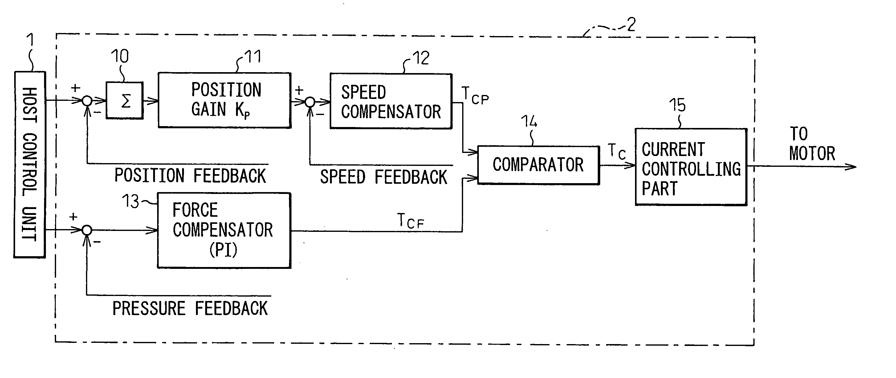
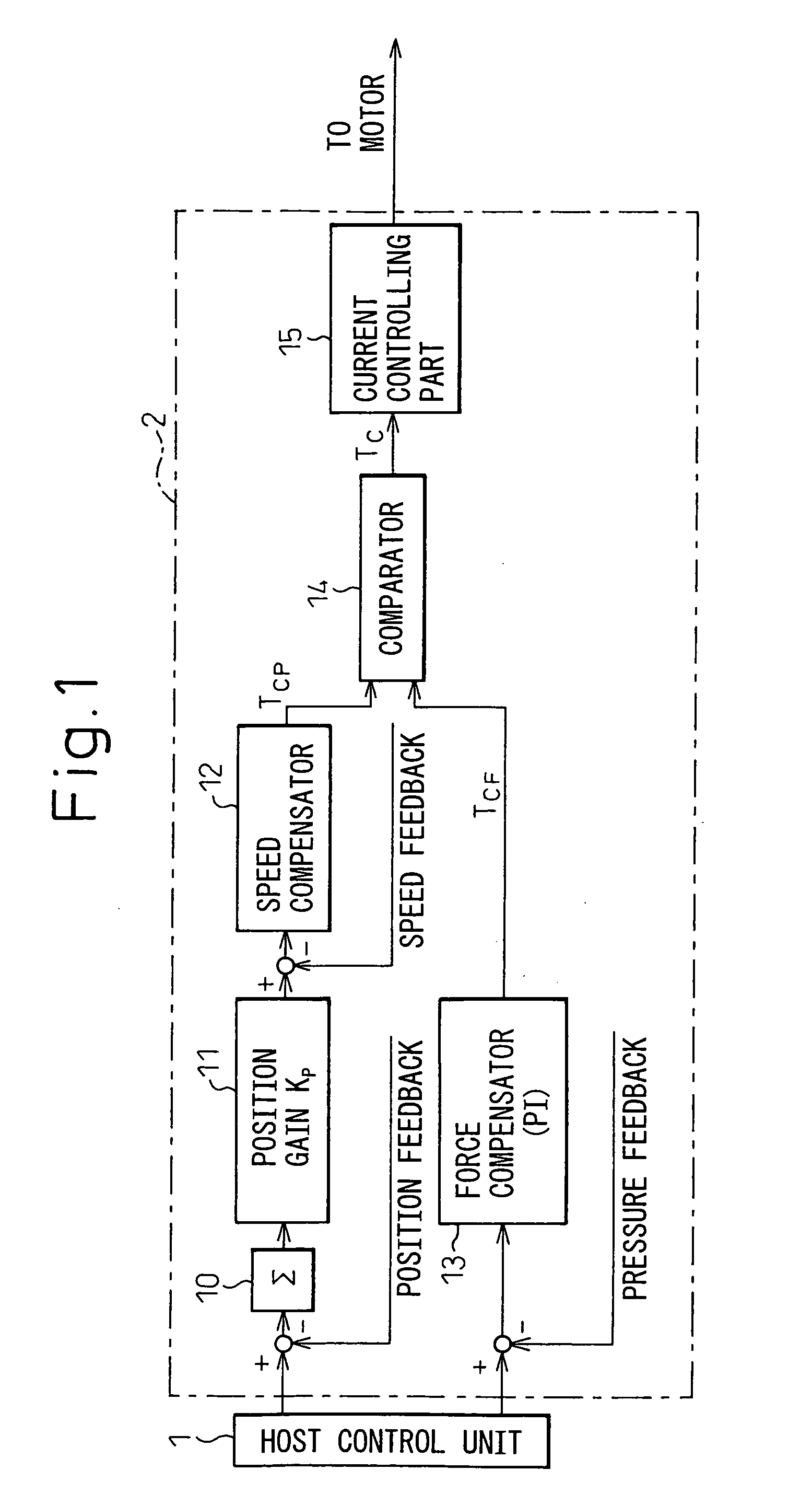
[0031]FIG. 1 is a block diagram of a servo motor control unit according to the present invention. In FIG. 1, reference numeral 1 is a numerical control unit or other host control unit for controlling a press machine or a bending machine or other press-forming machine. Further, reference numeral 2 indicates a motor control unit according to the present invention. FIG. 1 is expressed as a functional block diagram, but specifically the functional blocks are comprised of a processor for realizing these functions and a memory such as ROM, RAM and the like.

[0032] A servo motor of the press-forming machine for driving a die fastening member having a movable die mounted thereon is provided with a position detector and speed detector for detecting a position and speed thereof. Note that the servo motor may also be provided with the speed detector and the die fastening member having the movable die mounted thereon may also be provided with the position detector for detecting the position ther...

second embodiment

[0054] The servo motor control unit 3 of this second embodiment subtracts from the position command from the host control unit 1 the position feedback value detected by the position detector and fed back at the position control processing part, obtains the position error by the error counter 1 etc. and multiplies the position error with the position gain KP for position feedback processing so as to obtain the speed command VCP. On the other hand, the pressure control processing part subtracts from the pressure command simultaneously output from the host control unit 1 with the position command the pressure feedback value from the pressure sensor to obtain the pressure error and multiplies the pressure error with the focus gain KF for pressure feedback processing so as to obtain the speed command VCF in the pressure control.

[0055] The comparator 17 compares the speed command VCP obtained by position feedback processing of the position control processing part and the speed command VCF...

fourth embodiment

[0071]FIG. 5 is a block diagram of a servo motor control unit 5 according to the present invention. This fourth embodiment is also a unit 5 for controlling a servo motor for driving one of the dies subjected to die cushion control and differs from the third embodiment shown in FIG. 4 only in that acceleration feedback control is incorporated into the fourth embodiment. The rest is the same. In FIG. 5, elements the same as the third embodiment of FIG. 4 are assigned the same reference numerals.

[0072] In this fourth embodiment, the control unit integrates the speed feedback (at block indicated by reference numeral 20) to obtain the feedback value of acceleration, multiplies this obtained acceleration feedback value with the gain (at block indicated by reference numeral 21) to obtain a feedback value of the torque command, obtains the error between the obtained feedback value and torque command, and uses that error as the input to the current controlling portion 15.

[0073] In the fourt...


PUM


Abstract

A servo motor for driving a die is provided with position and speed detectors. Further, a pressure sensor for detecting the pressure applied to a workpiece is provided. In the servo motor control unit, the smaller one of the speed command obtained by feedback control of the position and the speed command obtained by the pressure feedback control is selected as an output of a comparator. Based on the speed command output from the comparator, feedback control of the speed is performed and the servo motor is driven. In the state where the die does not press against the workpiece, a pressure error is large, the speed command by pressure control becomes large, and the speed command by position control becomes small. Therefore, position control is performed. When the workpiece is pressed, the position error increases, and the pressure error decreases, a speed command by pressure control is employed and pressure control is performed.

Description

BACKGROUND OF THE INVENTION [0001] 1. Field of the Invention [0002] The present invention relates to a servo motor control unit for a press machine or bending machine or a other press-forming machine driven by a servo motor. [0003] 2. Description of the Related Art [0004] In a press machine or in a bending machine for bending a metal material, etc., normally oil pressure is used as the drive source for opening and closing the die, but there is also known an electric servo press which uses a servo motor to drive a die fastening member. [0005] In this electric servo press, use is made of a method of controlling a position of a movable die while machining a workpiece and a method of controlling a position of a movable die and, when a workpiece and a movable die abut each other and start a press operation, restricting an output of a servo motor for driving the movable die to maintain a constant pressure in control while machining the workpiece. [0006] However, we searched for patent doc...

Claims


Application Information

Patent Timeline
IPC IPC(8): G05D16/00
CPCB30B15/0094B30B15/148G05B2219/42092G05B2219/41202G05B2219/42087G05B19/416
Inventor IWASHITA, YASUSUKEOKITA, TADASHIKAWAMURA, HIROYUKI
Owner FANUC LTD
Why Eureka
Try Eureka