Circuit for multifrequency band radar level gauge

a radar level gauge and multi-frequency band technology, applied in the field of level measurement, can solve the problems of low phase noise and a rather narrow bandwidth, and achieve the effect of signal receiving

Inactive Publication Date: 2006-01-19
ROSEMOUNT TANK RADAR
View PDF30 Cites 29 Cited by
  • Summary
  • Abstract
  • Description
  • Claims
  • Application Information

AI Technical Summary

Benefits of technology

[0022] One advantage with the level gauge according to the invention is that it is possible to measure the surface level of a product by use of switching between different frequencies bands. Thus it will not be necessary to change the level gauge equipment operating on a certain frequency band to another level gauge equipment operating on another frequency band that is better suited for the conditions prevailing in the tank. It will also be possible to perform the level gauging by measurements on more than one frequency band for the same product in the tank. This may be performed by an automatic switching between the available frequency bands, whereafter the results of the measurements performed at different frequency bands may be compared and analysed for a determination of the most accurate value of the level of the surface of the product inside the tank.
[0023] One further advantage with a radar level gauge according to the invention aspect is that a signal received from the radar can be made more advanced and analyzed by means of a comparison of different spectra. Judgements of which echo from the surface of the product in the tank that is the most accurate and which echoes that may be disregarded as disturbance echoes are made available by the present invention.

Problems solved by technology

This method gives a low phase noise, but a rather narrow bandwidth.

Method used


Image

  • Circuit for multifrequency band radar level gauge
  • Circuit for multifrequency band radar level gauge
  • Circuit for multifrequency band radar level gauge

Examples


Embodiment Construction

[0027] A number of embodiments of the present invention supported by the enclosed figures will be disclosed in the following.

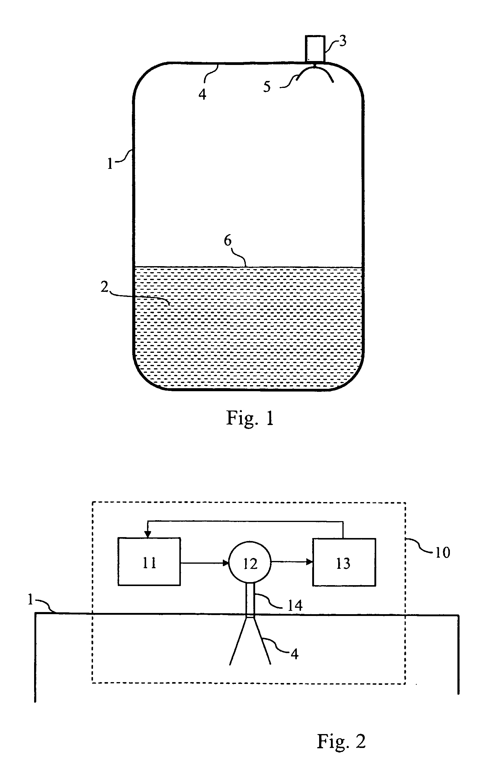
[0028] An application of a radar level gauge is shown in FIG. 1. A tank 1 is used for storing a product 2. The product may be such as oil, refined products, chemicals and liquid gas, or may be a material in powder form. A radar 3 is attached to the roof 4 of the tank 1. A microwave beam is transmitted from the radar via an antenna 5 at the interior of the tank. The transmitted beam is reflected from the surface 6 of the product and is received by the antenna 5. By means of a comparison and evaluating of the time lap between transmitted and reflected beam in a measuring and controlling unit, a determination of the level of the product surface 6 in a known manner is performed. The microwave may be transmitted from the antenna as a free radiated beam or via a wave guide (not shown), which communicates with the product. The radar level gauge as shown in FIG. 1 is...


PUM


Abstract

A circuit for a radar level gauge for measuring the level of the surface of a product stored in a container, wherein the gauge includes a radar for transmitting microwave signals from a multiband antenna unit towards the surface for receiving microwave signals reflected by the surface and for determining the level based on an evaluation of the time lapsed between the received and the transmitted signals and said radar operating on at least two different frequency bands. The circuit includes: a first microwave provision means for providing a microwave signal of a first frequency band having a first center frequency, a second microwave provision means for providing a microwave signal of a second frequency band having a second center frequency. The ratio between the second and the first center frequency is quantified as at least greater than 1.5:1 and preferably greater than 2:1. Switches are operated by means of a control signal for switching the circuit to operate on said first frequency band or said second frequency band.

Description

TECHNICAL FIELD [0001] The present invention relates to level measurement in industrial processes, wherein the invention is used for measurement of product level in a storage tank of the type used in industrial applications using a microwave level gauge. More specifically, the present invention relates to a circuit for providing the radar level gauge with microwaves optionally operating on at least two different frequency bands and a method for the generation of said different microwave frequency bands. BACKGROUND OF THE INVENTION AND RELATED ART [0002] There is known in the art to measure the level of the surface of a product stored in a tank by means of a radar level gauge. Such devices are disclosed in a number of documents. As an example of such a document, it will here be referred to patent document U.S. Pat. No. 4,665,403. [0003] Radar level gauges for use, as an example within the processing industry, must be able to function under very different conditions. The product store...

Claims


Application Information

Patent Timeline
Patent Type & Authority Applications(United States)
IPC IPC(8): G01S13/08G01F23/284G01S13/34G01S13/88H01Q1/22H01Q5/00H01Q13/02H01Q21/06
CPCG01F23/284G01S13/34G01S13/347H01Q21/065H01Q1/22H01Q1/225H01Q13/0275G01S13/88
Inventor JIRSKOG, ANDERS
Owner ROSEMOUNT TANK RADAR
Why Eureka
Try Eureka