Optical transmission system with two-mode ring protection mechanism for prioritized client signals

a protection mechanism and transmission system technology, applied in the field of optical transmission systems, can solve the problems of device, lack of consideration for bandwidth usage in normal situations, and failure to efficiently use the full available network capacity, so as to achieve enhanced fault tolerance, more efficient bandwidth usage, and higher service availability

Inactive Publication Date: 2006-01-19
FUJITSU LTD
View PDF4 Cites 56 Cited by
  • Summary
  • Abstract
  • Description
  • Claims
  • Application Information

AI Technical Summary

Benefits of technology

[0011] In view of the foregoing, it is an object of the present invention to provide an optical transmission system that ...

Problems solved by technology

Since this protection system always assigns two paths to carry the same service signals in preparation for a possible link failure, the actual usage of bandwidth is at most 50 p...

Method used


Image

  • Optical transmission system with two-mode ring protection mechanism for prioritized client signals
  • Optical transmission system with two-mode ring protection mechanism for prioritized client signals
  • Optical transmission system with two-mode ring protection mechanism for prioritized client signals

Examples


Embodiment Construction

[0026] Preferred embodiments of the present invention will be described below with reference to the accompanying drawings, wherein like reference numerals refer to like elements throughout.

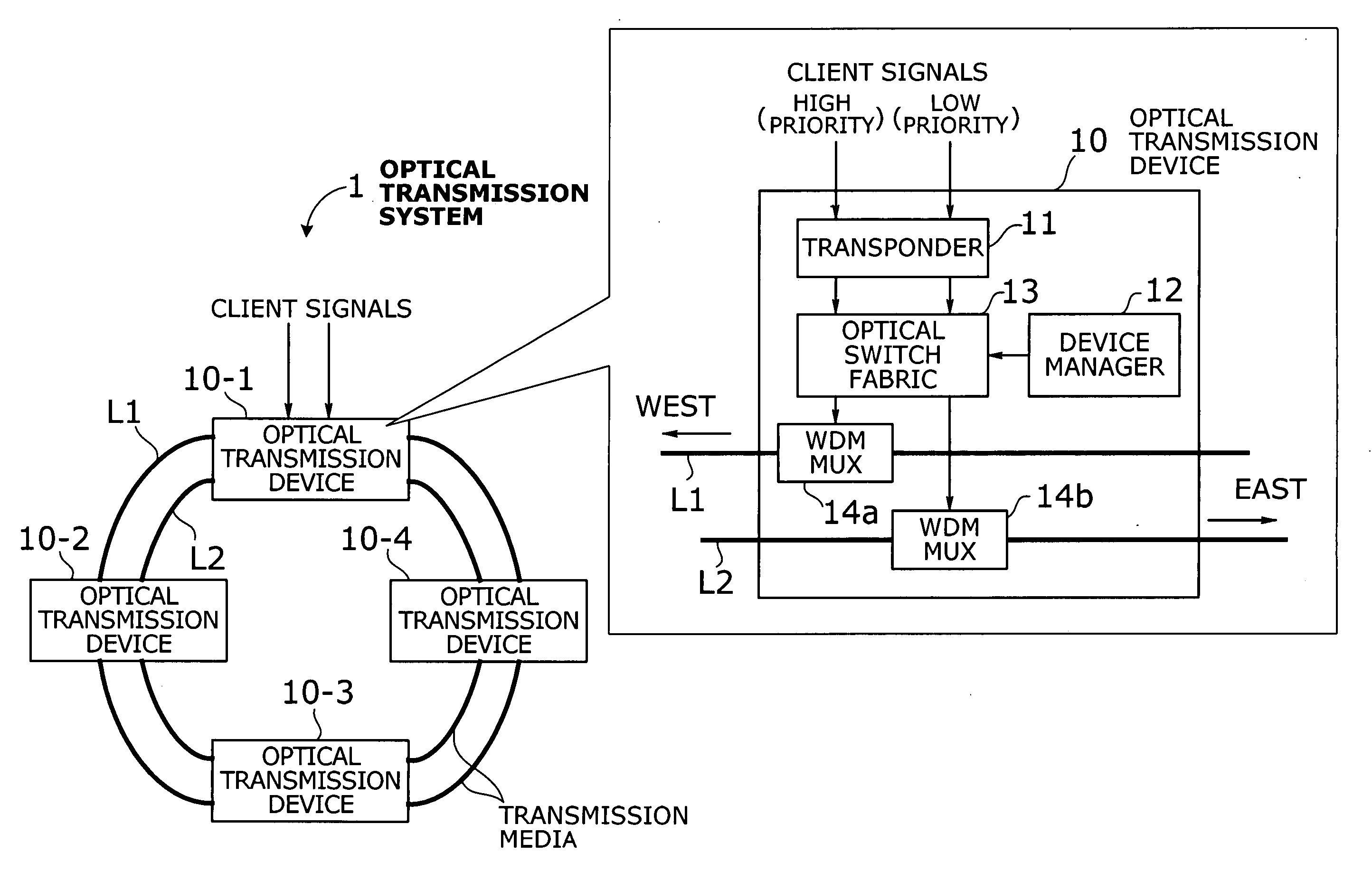
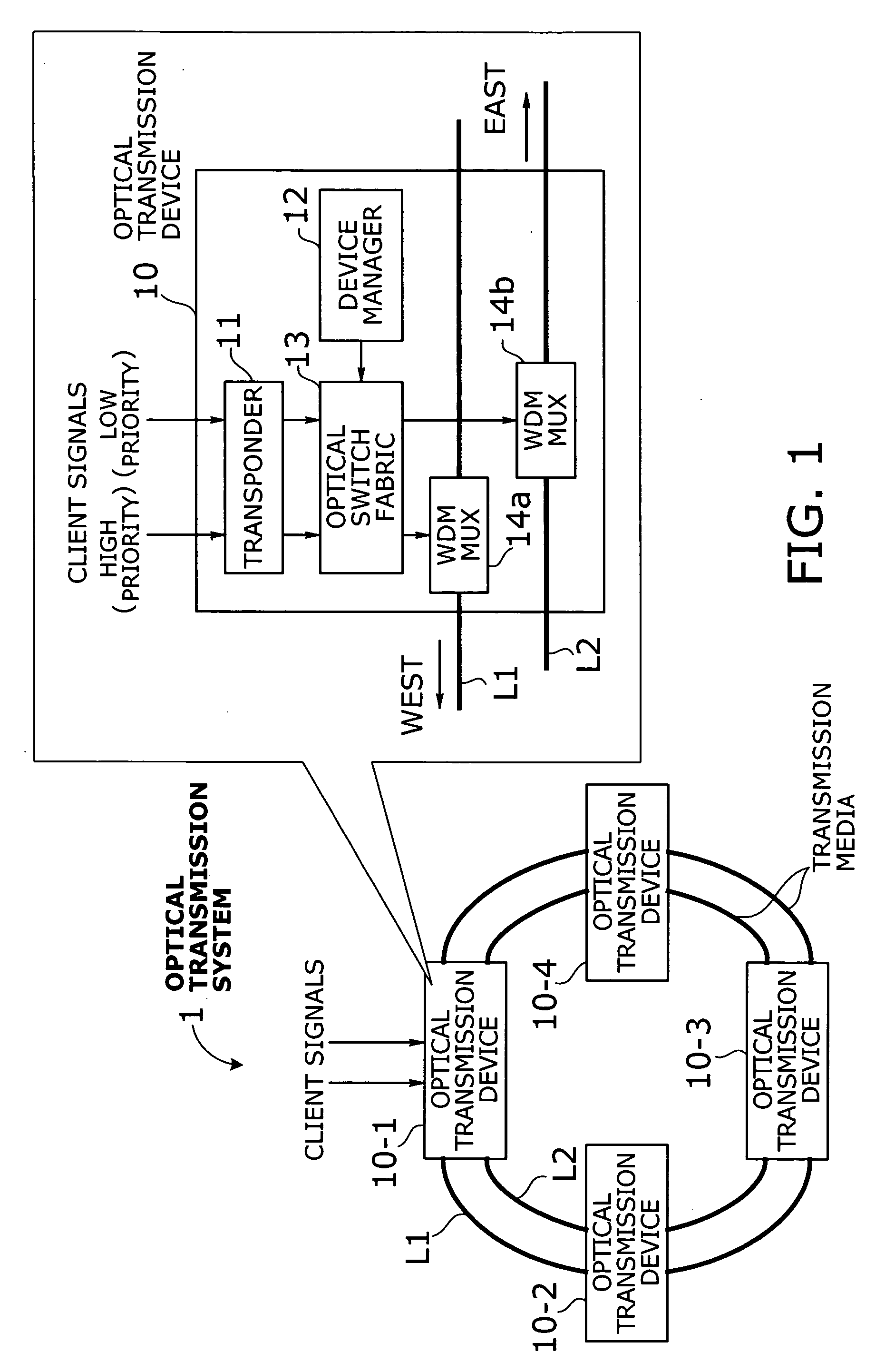
[0027]FIG. 1 is a conceptual view of an optical transmission system according to an embodiment of the present invention. The illustrated optical transmission system 1 is a WDM ring network involving a chain of four nodes 10-1 to 10-4 (collectively referred to by the reference numeral “10”) connected in a dual ring topology by two fiber-optic transmission lines (“lines” for short) L1 and L2. Each optical transmission device 10 contains a transponder 11, a device manager 12, an optical switch fabric 13, and WDM multiplexers 14a and 14b. Their functions are described below.

[0028] The transponder 11 converts incoming client signals into WDM signals to be added to the network traffic on the ring. The client signals are classified into those with a high priority and those with a low priority in terms ...


PUM


Abstract

An optical transmission system that offers more efficient bandwidth usage in normal operation, as well as enhanced fault tolerance for higher service availability. A transponder converts high-priority and low-priority client signals into high-priority and low-priority wavelength signals to be added to network traffic. An optical switch fabric normally delivers high-priority and low-priority wavelength signals to high-priority and low-priority paths, respectively, where the two paths run in opposite directions. Such signals and paths are prioritized in terms of survivability against network failure. In case of a network failure, the optical switch fabric performs protection switching in either duplicate switching mode or path switchover mode depending on network failure information and drop wavelengths of each optical transmission device. In duplicate switching mode, high-priority wavelength signals are directed to both the high-priority and low-priority paths. In path switchover mode, they are routed to the low-priority path, instead of the high-priority path.

Description

CROSS-REFERENCE TO RELATED APPLICATIONS [0001] This application is based upon and claims the benefits of priority from the prior Japanese Patent Application No. 2004-208237, filed on Jul. 15, 2004, the entire contents of which are incorporated herein by reference. BACKGROUND OF THE INVENTION [0002] 1. Field of the Invention [0003] The present invention relates to an optical transmission system, and more particularly to an optical transmission system that transports optical signals with optical wavelength-division multiplexing (WDM) techniques. [0004] 2. Description of the Related Art [0005] WDM technology enables many transmission signals to be carried over a single fiber-optic medium, assigning different optical wavelengths to different communication channels. Recent years have seen a remarkable progress in development of WDM networks as a key technology for data communication infrastructures. A widely used WDM backbone structure is ring network systems, which is formed from a plur...

Claims


Application Information

Patent Timeline
IPC IPC(8): H04B10/08H04B10/00H04B10/03H04B10/035H04B10/077H04B10/079H04B10/27H04B10/275H04J14/00H04J14/02H04L12/437H04L69/40
CPCH04J14/0227H04J14/0241H04J14/0295H04J14/0283
Inventor MIYAZAKI, KEIJI
Owner FUJITSU LTD
Why Eureka
Try Eureka