Fuel cell system

a fuel cell and system technology, applied in the field of fuel cell systems, can solve the problems that the electrical potential difference and current measured during power generation do not meet the aforementioned linear relation, and achieve the effects of reducing the power generation efficiency of the fuel cell, reducing the power generation performance of the cell, and increasing the supply of reactive gas

Inactive Publication Date: 2006-01-19
NISSAN MOTOR CO LTD +1
View PDF2 Cites 25 Cited by
  • Summary
  • Abstract
  • Description
  • Claims
  • Application Information

AI Technical Summary

Benefits of technology

[0013] (4) When power generating performance of a cell is reduced due to deterioration in electrode catalyst or ion conductivity or the like of the electrolyte membrane with passage of time, the electrical potential difference and the current measured during power generation does not satisfy the aforementioned linear relation, even if the supply of the reactive gas is increased. In this case, gas exhaust not contributing to the power generating reaction is increased, whereby the power generation efficiency of the fuel cell is reduced.

Problems solved by technology

However, problems as will be described hereunder are involved in the aforementioned system.
(4) When power generating performance of a cell is reduced due to deterioration in electrode catalyst or ion conductivity or the like of the electrolyte membrane with passage of time, the electrical potential difference and the current measured during power generation does not satisfy the aforementioned linear relation, even if the supply of the reactive gas is increased.

Method used


Image

  • Fuel cell system
  • Fuel cell system
  • Fuel cell system

Examples


Embodiment Construction

[0021] An embodiment of the present invention will be explained below with reference to the drawings, wherein like members are designated by like reference characters. In the description hereunder, explanation will be given to an example of applying the present invention to a solid polymer fuel cell. However, the present invention is not limited thereto, and can be applied to other type of the fuel cell such as a solid oxide fuel cell.

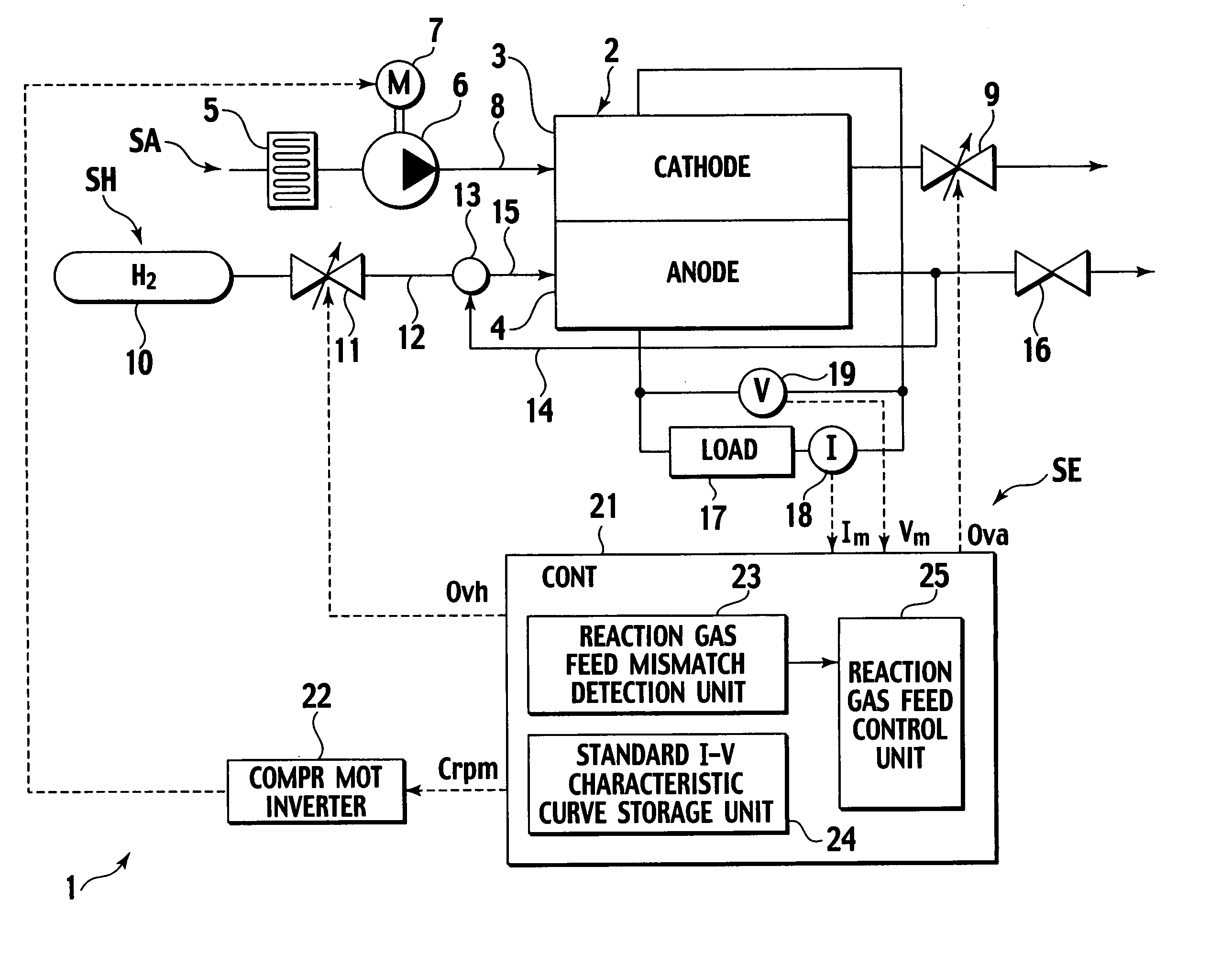
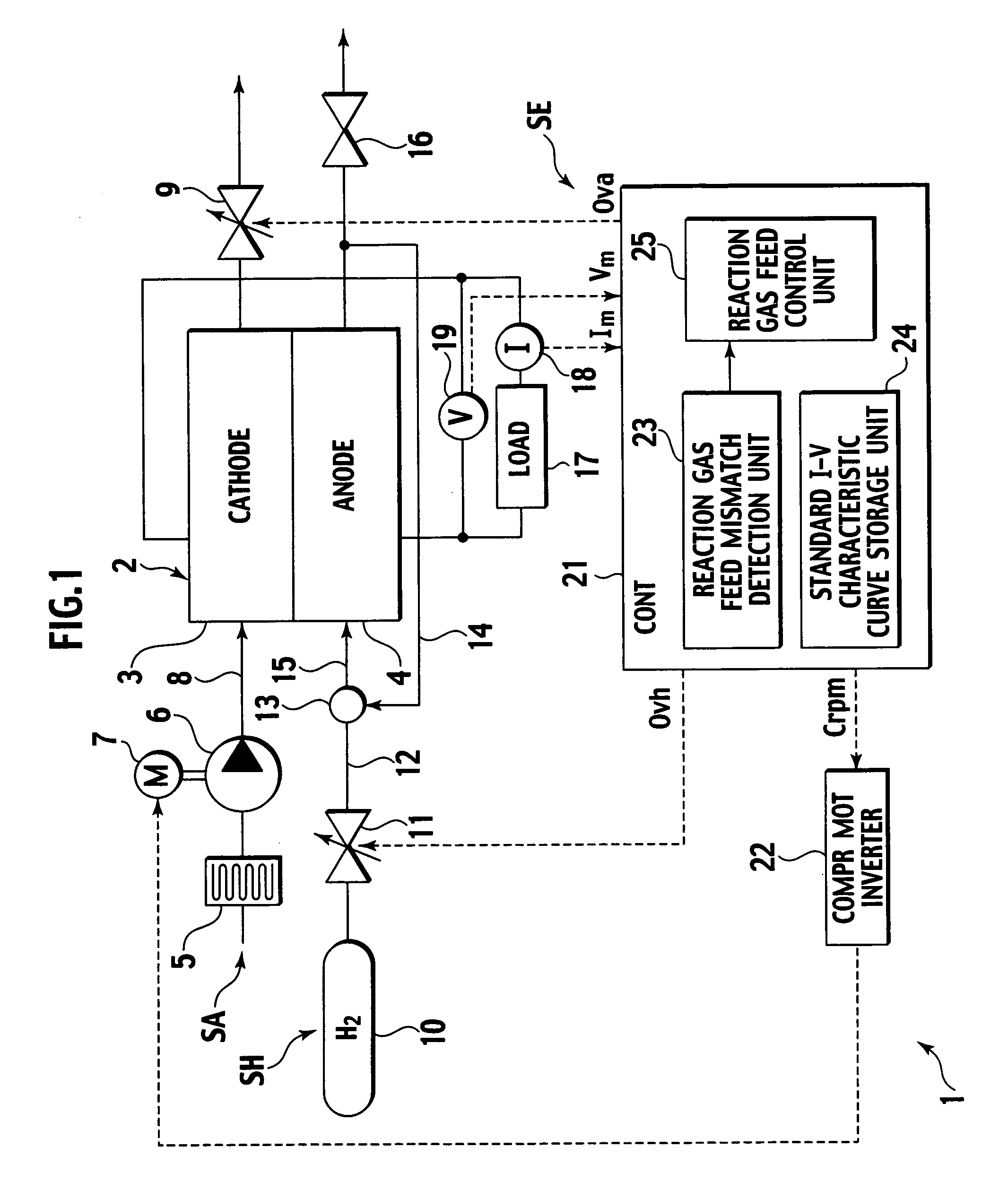
[0022] As shown in FIG. 1, a fuel cell system 1 includes a fuel cell 2, an air supply system SA for supplying air as an oxidizer gas to a cathode 3 of the fuel cell 2, a hydrogen gas supply system SH for supplying hydrogen gas as a fuel gas to an anode 4 of the fuel cell 2, a load 17, and an instrumentation and control system SE.

[0023] The fuel cell 2 is a solid polymer fuel cell which generates power through an electrochemical reaction between oxygen in the air supplied to the cathode 3 and hydrogen gas supplied to the anode 4 as reaction gases. The...


PUM

PropertyMeasurementUnit
output voltageaaaaaaaaaa
current-voltageaaaaaaaaaa
current-voltage characteristicaaaaaaaaaa

Abstract

A fuel cell system which includes: a fuel cell fed with a reaction gas for generating power; an output detection unit which detects output current and voltage of the fuel cell; a storage unit which stores a standard current-voltage characteristic of the fuel cell, from which a standard voltage of the fuel cell at an output current thereof is obtainable; and a gas feed mismatch detection unit which detects a gas feed mismatch of the reaction gas, based on a comparison between the detected output voltage of the fuel cell and the standard voltage at the detected output current, obtained from the standard current-voltage characteristic stored.

Description

BACKGROUND OF THE INVENTION [0001] 1. Field of Invention [0002] The present invention relates to a fuel cell system, particularly to a technology to optimize feed rate of fuel gas and oxidizer gas to a fuel cell in a fuel cell system. [0003] 2. Description of Related Art [0004] Fuel cell is an electrochemical device which converts the chemical energy of a chemical reaction directly into electrical energy. A typical fuel cell consists of an electrolyte membrane and anode and cathode compartments sandwiching the electrolyte membrane therebetween, in which fuel gas is fed continuously to the anode compartment, oxidizer gas is fed continuously to the cathode compartment, and oxygen from the oxidizer gas and hydrogen contained in the fuel gas electrochemically reacts to generate electric power. The fuel cells are classified into alkaline fuel cell (AFC), phosphoric acid fuel cell (PAFC), molten carbonate fuel cell (MCFC), solid oxide fuel cell (SOFC) and polymer electrolyte fuel cell (PE...

Claims


Application Information

Patent Timeline
Patent Type & Authority Applications(United States)
IPC IPC(8): H01M8/04
CPCH01M8/04089H01M8/04559Y02E60/50H01M8/04753H01M8/04589
Inventor KOKUBO, MITSUHIRO
Owner NISSAN MOTOR CO LTD
Why Eureka
Try Eureka