Process for low temperature, dry etching, and dry planarization of copper

a technology of copper and dry etching, applied in the direction of decorative arts, decorative surface effects, electrical equipment, etc., to achieve the effect of rapid, cost-effective and environmental-friendly

Inactive Publication Date: 2006-01-19
KULKARNI NAGRAJ S
View PDF7 Cites 8 Cited by
  • Summary
  • Abstract
  • Description
  • Claims
  • Application Information

AI Technical Summary

Benefits of technology

[0013] The volatility diagram for Cu—Cl was constructed at temperatures between 50 and 200° C. based on the procedure developed by Lou, Mitchell and Heuer [43,44]. Examination of the volatility diagram revealed that Cu3Cl3(g) had the highest vapor pressure. However the equilibrium vapor pressure of Cu3Cl3(g) is not sufficient for the purpose of dry etching of copper at temperatures below 200° C. At temperatures greater than 200° C. and with chlorine pressures lower than that given by the isomolar point (FIG. 3), it is possible to etch copper without the formation of CuCl(c), due to the active oxidation of copper involving the Cu(c)-Cu3Cl3(g) vaporization reaction. The subject invention relates to the etching of copper at low temperatures (25° C.) by using the metastable CuCl2(c)-Cu3Cl3(g) volatilization reaction in the presence of hydrogen (FIGS. 5, 6). In a specific embodiment, the subject invention relates to a multi-step etch process (FIG. 10), which first includes the rapid and preferential formation of CuCl2(c) followed by its removal using the above reaction. The successful implementation of this low-temperature, dry etch process can provide a rapid, cost-effective and environment-friendly alternative to the Cu damascene process. A further application of this multi-step process for the reactive ion planarization (RIP) of copper may offer an attractive alternative to the chemical mechanical planarization (CMP) step in the damascene process.

Problems solved by technology

However the equilibrium vapor pressure of Cu3Cl3(g) is not sufficient for the purpose of dry etching of copper at temperatures below 200° C. At temperatures greater than 200° C. and with chlorine pressures lower than that given by the isomolar point (FIG. 3), it is possible to etch copper without the formation of CuCl(c), due to the active oxidation of copper involving the Cu(c)-Cu3Cl3(g) vaporization reaction.

Method used


Image

  • Process for low temperature, dry etching, and dry planarization of copper
  • Process for low temperature, dry etching, and dry planarization of copper
  • Process for low temperature, dry etching, and dry planarization of copper

Examples


Embodiment Construction

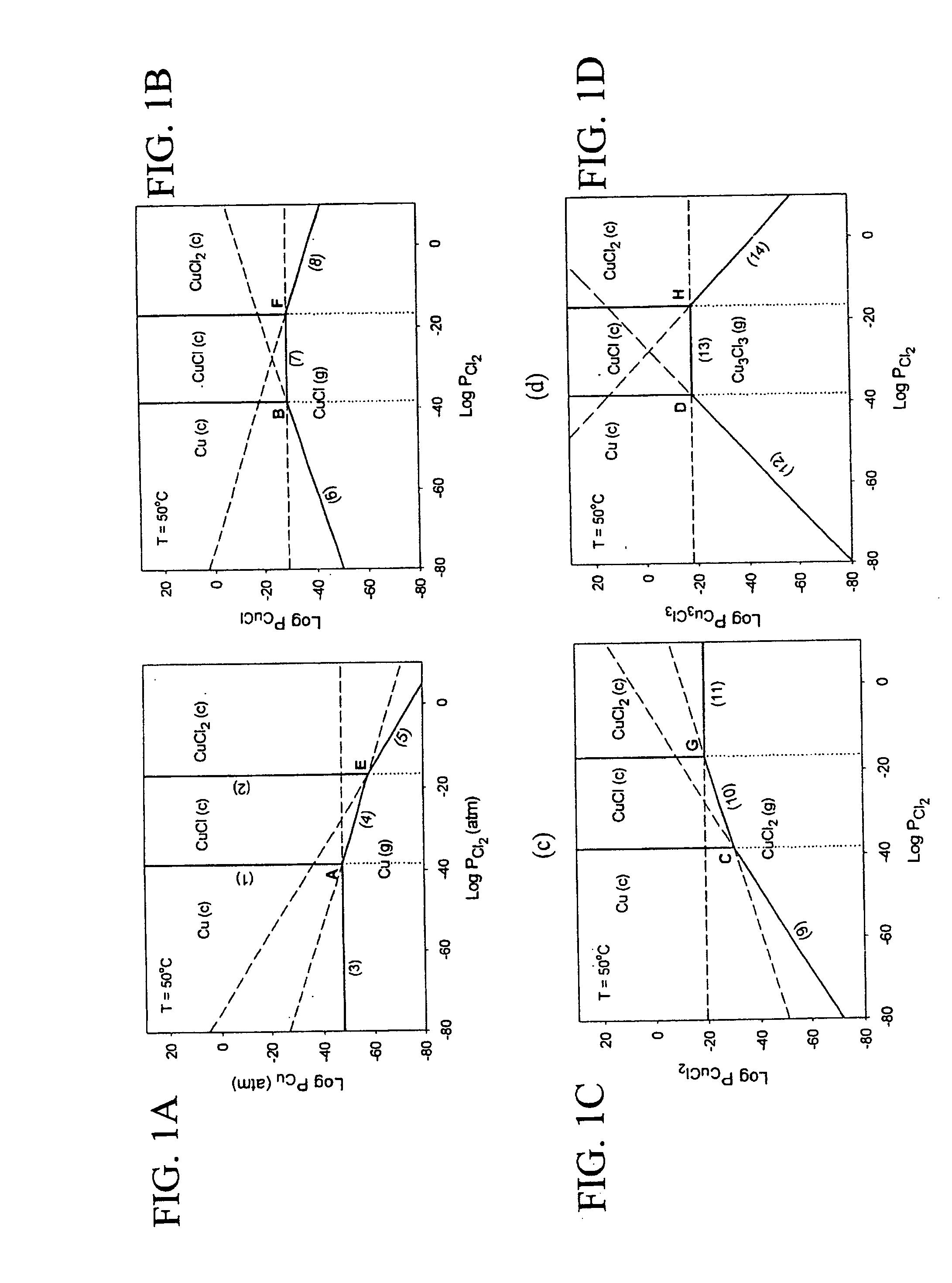
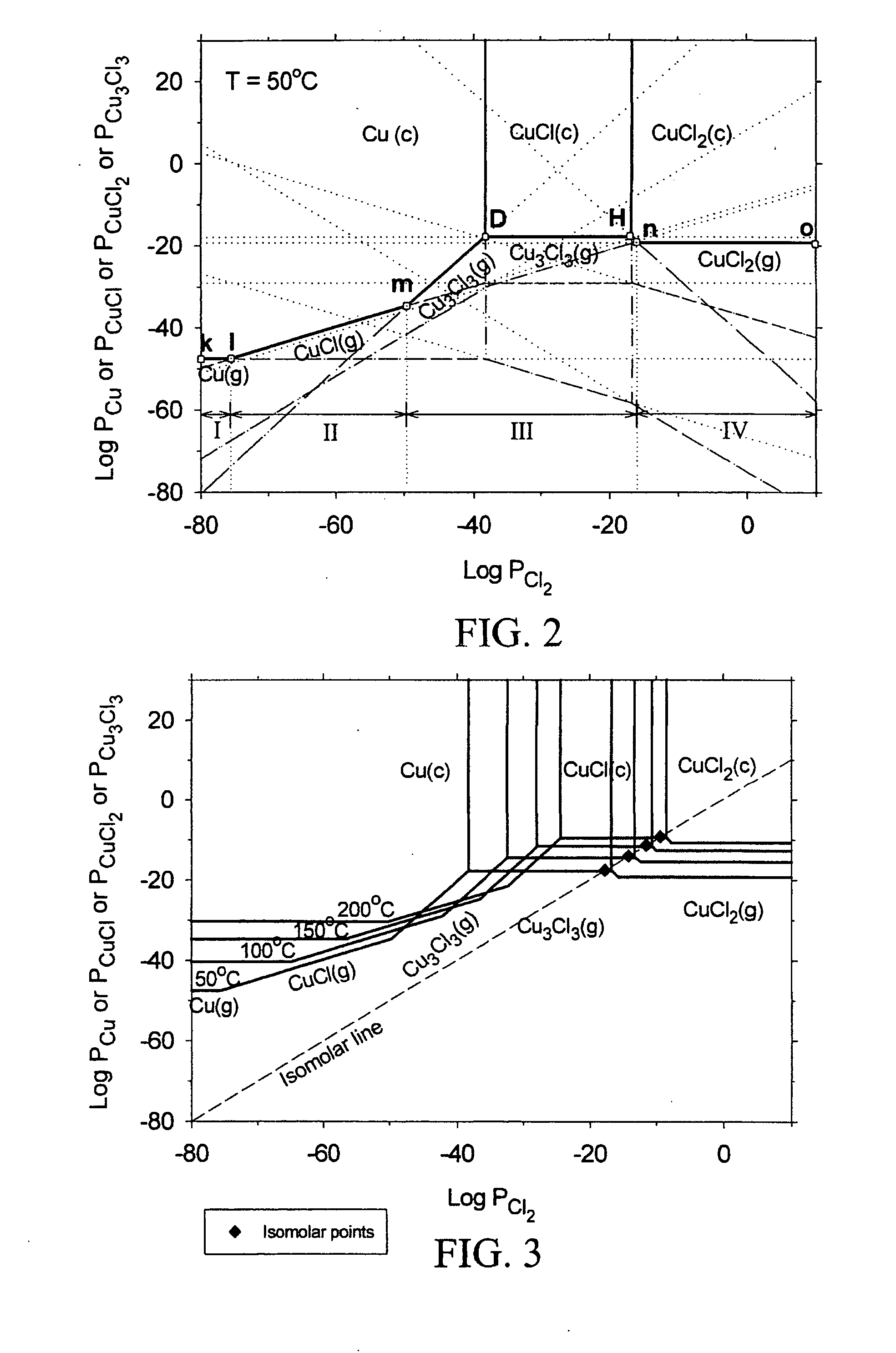
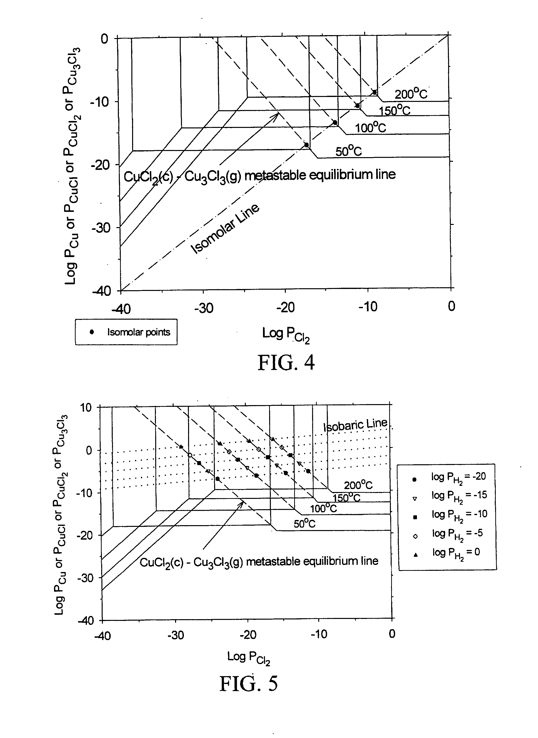
[0024] The subject invention pertains to a method and apparatus for etching copper (Cu). The subject invention can involve passing a halide gas over an area of Cu such that CuX, or CuX and CuX2, are formed, where X is the halide. Examples of halide which can be utilized with the subject matter include, but are not necessarily limited to, Cl, Br, F, and I. Once the CuX, or CuX and CuX2, are formed the subject invention can then involve passing a reducing gas over the area of Cu for a sufficient time to etch away at least a portion of the CuX, or CuX2 are produced when the halide gas is passed over the area of Cu, the reducing gas can be passed until essentially all of the CUX2 is etched and at least a portion of the CuX is etched. Examples of reducing gases which can be utilized with the subject invention include, but are not necessarily limited to, hydrogen gas and hydrogen gas plasma. The subject invention can accomplish the etching of Cu by passing the reducing gas over the Cu so ...


PUM

PropertyMeasurementUnit
temperatureaaaaaaaaaa
temperaturesaaaaaaaaaa

Abstract

The subject invention pertains to a method and apparatus for etching copper (Cu). The subject invention can involve passing a halide gas over an area of Cu such that CuX, or CuX and CuX2, are formed, where X is the halide. Examples of halides which can be utilized with the subject matter include, but are not necessarily limited to, Cl, Br, F, and I. Once the CuX, or CuX and CuX2, are formed the subject invention can then involve passing a reducing gas over the area of Cu for a sufficient time to etch away at least a portion of the CuX, or CuX2, respectively. With respect to a specific embodiment in which CuX and CuX2 are produced when the halide gas is passed over the area of Cu, the reducing gas can be passed until essentially all of the CUX2 is etched and at least a portion of the CuX is etched. Examples of reducing gases which can be utilized with the subject invention include, but are not necessarily limited to, hydrogen gas and hydrogen gas plasma. The subject invention can accomplish the etching of Cu by passing the reducing gas over the Cu so as to be on a CuX2—Cu3X2 metastable line when etching CuX2 and to be a CuY—CuX metastable line, where Y is the reducing gas element, when etching CuX. FIGS. 5, 6, and 8, show such metastable lines for Cu, with X being Cl, from temperatures ranging from 50° C. to 200° C. These can be extrapolated to other temperatures, for other halides, and/or other reducing gases. The subject invention can be used to, for example, etch partial into a layer of Cu, through a layer of Cu, or to smooth a Cu surface.

Description

CROSS-REFERENCE TO RELATED APPLICATION [0001] This application is a continuation of U.S. patent application Ser. No. 10 / 285,179, filed Oct. 31, 2002, which claims the benefit of U.S. provisional patent application Ser. No. 60 / 335,641, filed Oct. 31, 2001, which are hereby incorporated by reference in their entirety.BACKGROUND [0002] Background for the subject technology can be found in the pioneering work by the late Carl Wagner [32] on the active-passive oxidation of Si and the work by Lou, Mitchell and Heuer [33] on treatment of volatility diagrams. [0003] The replacement of aluminum with copper as an interconnect material in ULSI structures is being actively considered in the semiconductor industry [1-7]. Compared to aluminum, copper has a lower electrical resistivity and significantly larger electromigration resistance. The utilization of copper interconnects is expected to improve chip performance due to lower RC time delays and power dissipation. Two basic processes for copper...

Claims


Application Information

Patent Timeline
Patent Type & Authority Applications(United States)
IPC IPC(8): H01L21/302C23F4/00H01L21/3213
CPCH01L21/32136C23F4/00
Inventor KULKARNI, NAGRAJ S.
Owner KULKARNI NAGRAJ S
Why Eureka
Try Eureka